Universal DH
| Language: | English • 中文(简体) |
|---|
Contents
Universal DH Kinematics
Introduction
softMC has supports many kinds of robot kinematics, several firmware coded kinematic models and one general user-defined kinematics (written by user in C-code).
All firmware coded kinematics (SCARA,DELTA, PUMA, …) assume an ideal kinematics model where angles between segments are at an exactly the predefined value (e.g. 90 deg). This is not always the case.
For example in PUAM robot kienamtics it is assumed that angle between first and second joint is exactly 90 degrees, in this model (model=2) there is no option to define different angle or an angle correction.
Only segment lengths can be manually entered. In addition to that at PUMA kinematic there exist a model constraint that all last 3 rotation axes (J4,J5,J6) must meet at same point.
For general robots:
- Up to 6DOF
- Must be Open-chain kinematics (no parallel robots)
There are two types of universal kinematics:
- PUMA “like” 6-DOF
- General Open-Chain Kinematics
Difference Between Model = 20 and Model = 19
- Model 19 is specially tailored for PUMA-like robots. This means that robot need to satisfy the following conditions:
All axes are rotary.
There is exactly 6 DOF’s (axes)
Robot configuration flags (arm, elbow, wrist) are defined according most similar PUMA robot. - Model 20 is general open-chain model, axes can be bot rotary or linear and the only limitation is that there can not be more then 6 DOF (axes).
Robot configuration flags are defined according user-defined function calls.
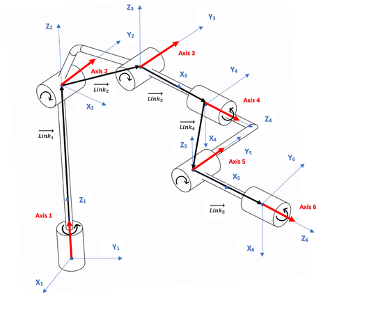
Geometry Definition
Robot geometry is defined by two arrays:
- Link [i] [j] (segment length):
- Where i = 1-6 for segments 1 to 6
- Where j = 1-3 for coordinates x,y,z
- Segment length coordinates are relative to base coordinate origin placed at connection point with previous segment (without any rotation)
- Axis [i] [j] (joint axis direction):
- Where i = 1-6 for segments 1 to 6
- Where j = 1-3 for coordinates x,y,z
- Axis rotation vector relative to base coordinate origin)�In case of translational joint it is direction of the axis movement.
User Functions
In case of general open-chain model (20) the robot configuration can not be automatically defined therefor we are using the following user functions:
- Import_c UDH_SET_MAX_CFG(byval as long,byval as long) as long Setting the max number of robot configurations (for PUMA it is 8)
- Import_c UDH_SET_CFG(byval as long, byval as long,byval as joint of xyzr) as long Setting representative robot configuration for each configuration flag.
Flag values are sett according to bitmask in same ways as in ToJoint function.
Example (SCARA):
- ?UDH_SET_MAX_CFG(elementid,2)
- ?UDH_SET_CFG(elementid,0,{0,-45,0,0}) ' lefty
- ?UDH_SET_CFG(elementid,1,{0,45,0,0}) ' righty
6R Robot With Offset Wrist
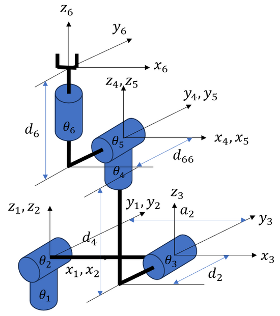
The following example shows how to assign the values of Link[i][j] and Axis[i][j] for the following kinematic model of a PUMA robot with wrist offset (model 19).
Note that a2 and d6 bellow must not be set to zero in this model.
After setting the values of Link[i][j] and Axis[i][j] according to the example bellow, the actual zero reference position of the robot can be changed using the ThetaOffset property.
Link[1][1] = a1 ' along x1 (not shown)
Link[1][2] = 0
Link[1][3] = 0
Axis[1][1] = 0
Axis[1][2] = 0
Axis[1][3] = 1 ' rotation about z1
Link[2][1] = a2 ' along x2
Link[2][2] = 0
Link[2][3] = 0
Axis[2][1] = 0
Axis[2][2] = 1 ' rotation about y2
Axis[2][3] = 0
Link[3][1] = a3 ' along x3 (not shown)
Link[3][2] = d2 ' along y3
Link[3][3] = d4 ' along z3
Axis[3][1] = 0
Axis[3][2] = 1 ' rotation about y3
Axis[3][3] = 0
Link[4][1] = 0
Link[4][2] = 0
Link[4][3] = 0
Axis[4][1] = 0
Axis[4][2] = 0
Axis[4][3] = 1 ' rotation about z4
Link[5][1] = 0
Link[5][2] = d66 ' along y5
Link[5][3] = d6 ' along z5
Axis[5][1] = 0
Axis[5][2] = 1 ' rotation about y5
Axis[5][3] = 0
Link[6][1] = 0
Link[6][2] = 0
Link[6][3] = 0
Axis[6][1] = 0
Axis[6][2] = 0
Axis[6][3] = 1 ' rotation about z6
The following link values are used for this example: 𝑎1=0 𝑎2=700 𝑑2=−200 𝑎3=0 𝑑4=600 𝑑6=50 𝑑66=−90.
Following are a nember of representing joint values and the corresponding position and orientation of the TCP:
Pcmd = {0 , 0 , 0 , 0 , 0 , 0}
SetPoint = #{700 , -290 , 650 , 0 , 0 , 0}
Pcmd = {90 , 0 , 0 , 0 , 0 , 0}
SetPoint = #{290 , 700 , 650 , 0 , 0 , 90}
Pcmd = {0 , 90 , 0 , 0 , 0 , 0}
SetPoint = #{650 , -290 , -700 , 0 , 90 , 0}
Pcmd = {0 , 0 , 90 , 0 , 0 , 0}
SetPoint = #{1350 , -290 , 0 , 0 , 90 , 0}
Pcmd = {0 , 0 , 0 , 90 , 0 , 0}
SetPoint = #{790 , -200 , 650 , 0 , 0 , 90}
Pcmd = {0 , 0 , 0 , 0 , 90 , 0}
setPoint = #{750 , -290 , 600 , 0 , 90 , 0}
Pcmd = {0 , 0 , 0 , 90 , 90 , 90}
SetPoint = #{790 , -150 , 600 , 90 , 90 , 90}


