Teach Pendant Installation Guide
| Language: | English • 中文(简体) |
|---|

Product Overview
The softTP teach pendant (TP) is an add-on tool for softMC-based systems. It allows users to move the robot by means of jog keys, and to create and run complete robot programs written in MC-Basic.
The softTP touch screen interface enables quick and easy application development.

See Also (How to connect simple switch to CDHD):
How to connect simple switch to CDHD
Teach Pendant Hardware
- Touch screen
- Jog buttons
- Emergency switch
- Deadman switch
- Mode Selector switch
- Jig board for power, Ethernet communication and digital outputs
Teach Pendant Software
The following software components are provided with the softTP:
- Java Runtime Engine
- Java Web Server (HTML to KMAPI converter) and WWW folder (HTML files and Java scripts)
- softTP license (MCTP file)
- softTP programs and libraries (MC-Basic source code)
Product Label

Safety
Warnings

|
It is the user’s responsibility to follow all safety guidelines and precautions for working with robotic system. |
|
|
It is the user’s responsibility to connect the Emergency switch to the robotic system in accordance with safety standards and guidelines. |
|
|
It is the user’s responsibility to connect the Deadman switch to the robotic system in accordance with safety standards and guidelines. |
|
|
When handling the softTP teach pendant, be sure to grasp it with both hands. The softTP is equipped with a deadman switch to ensure user safety. You cannot operate the teach pendant unless the deadman switch is held down in the intermediate (Enable) position. Refer to the section Error! Reference source not found. |
|
|
Never use adhesive tape or other means to keep the deadman switch held down. Doing so is extremely dangerous as it may prevent the robot from stopping while operating in Manual mode. |
Handling and Maintenance
- Make sure cabling is secure and cannot be tripped over.
- Make sure cabling is not bent or crushed by other objects.
- Make sure cabling does not come into contact with sharp edges that can cause it to fray.
- Make sure the softTP is never set down in a manner in which operating elements may be mechanically damaged.
- Never place the softTP where it will be subject to high heat sources or direct sunlight.
- Avoid subjecting the softTP to mechanical shocks, excessive dust, humidity or strong magnetic fields.
- Do not use solvents or abrasive materials on the softTP. For cleaning use a soft cloth moistened with water or a mild cleaning agent.
- The softTP has a touch screen. Use only your finger to operate. Make sure no sharp objects come into contact with the screen.
Specifications
Technical Specifications
| Item | Specification |
|---|---|
| Processor | Intel®Atom™E3800/1.6 GHz single core |
| Memory | DDR3 4 GB |
| NAND | SSD 32 GB |
| Rating | 12-24 VDC, 1-0.5 A |
| LCD Screen | TFT LCD. 7-inch (163 x 104 mm). Resolution 800x480 pixel. Background lighting 24 LEDs. |
| Touch Screen | 4-wire analog-resistive. USB touch controller. |
| OS | Lubunto |
| LEDs | 3-color LED x 6 |
| SD/MMC | External SD card |
| USB | USB host |
| Keypad | -) keys. 4 screen navigation keys. 4 function keys (not used). |
| Switches | Emergency/Mode Select/Deadman |
| Communication | RS232/RS485/Ethernet. Selectable |
| Operating Temperature | 45°C max. ambient |
| Enclosure | IP54 |
| Compliance | CE |
Dimensions


Wiring
Teach Pendant Cable
The teach pendant cable is part of the softTP; it cannot be detached.
TP Cable Pin Assignments

TP Cable Connector - Male

| Part Number | A | ΦB | ΦC | ΦD | |
|---|---|---|---|---|---|
| SRC6A21-26P | mm | 98.0 | 31.0 | 20.4 | 12.2 |

Jig Board
TP Cable Interface on Jig Board - Female

| Part Number | A | ΦB | C(C') | D | E | F | G | |
|---|---|---|---|---|---|---|---|---|
| SRC6A21-26P | mm | 25.6 | 20.4 | 27.7 (25.5) | 14 | 2.3 | 32 | 26 |
 :
: 
IO Cable Interface on Jig Board - Pin Assignments
Example: connection to CDHD
- The Emergency and Deadman switches are connected to the safety circuit of the system (STO, safety relay) according to user requirements.

Example: connection to DDHD
- Different input order and no emergency switch connected. Green lines are bridges; red and black lines are from an outside source.

Emergency Switch
It is the user’s responsibility to connect the Emergency switch to the robotic system, and to follow all necessary safety guidelines and precautions.

Selector Switch

| Position | Symbol |
|---|---|
| Left | 
|
| Center | 
|
| Right | 
|
Deadman Switch
It is the user’s responsibility to connect the Deadman switch to the robotic system, and to follow all necessary safety guidelines and precautions.
Pressing or releasing the Deadman switch automatically and immediately stops the motion of all axes.

| Action | Position | Symbol | |
|---|---|---|---|
| If deadman switch is not pressed or is pressed too lightly.
Switch is off. |

|
Null | 
|
| If deadman switch is pressed with normal pressure.
Switch is on. |

|
Enable | 
|
| If deadman switch is pressed too hard.
Switch is off. |

|
Panic | 
|
Setup
Hardware Setup
The diagram below shows a typical system configuration.

- The softTP connects to the jig board by means of the teach pendant cable.
- The jig board: Receives 24 VDC power supply (provided by user); connects to the Ethernet switch by means of an Ethernet (RJ45) cable; connects to drive/s or an external IO module by means of an IO cable (provided by user).
- The three softTP switches – Mode Selector, Emergency and Deadman – are connected to the digital inputs of a drive, or to an external IO module, through the IO cable (provided by user).
- The Emergency and Deadman switches are connected to the safety circuit of the system (STO, safety relay) according to user requirements.
Software Setup
note: IPK files are for softMC 7 systems; ZIP files are for softMC 3 systems.
Using ControlStudio software, perform the following procedure:
- Install the Java Runtime Engine:
- Send JREx.x.x_xxx.IPK/ZIP file to softMC:
Tools > Firmware Update > File > Open. - Wait for the softMC to reboot (automatically).
- Send JREx.x.x_xxx.IPK/ZIP file to softMC:
- Install the Java Web Server and HTML (WWW folder) files:
- Send JAVA_FILES. .IPK/ZIP file to softMC:
Tools > Firmware Update > JAVA_FILES.IPK > Open - Wait for the softMC to reboot (automatically)
- Send JAVA_FILES. .IPK/ZIP file to softMC:
- Install and activate the softTP license:
- Make sure the MCTP file is in the ControlStudio working directory.
- In the ControlStudio Terminal, enter the following:

- Power cycle the system.
- On the user PC, create a dedicated folder for the set of MC-Basic teach pendant files, which define settings for softTP operation.
Extract the teach pendant files to that folder.
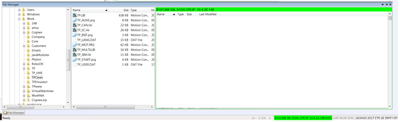
In the ControlStudio File Manager, navigate to and open the dedicated folder.
Select and drag all the MC-Basic teach pendant files from the PC File list (middle pane) to the Controller File list (right pane).
- In the Controller File list, locate the file TP_INIT.PRG.
Select and drag the file from the Controller File list to the PC File list.
Double-click to open TP_INIT.PRG for editing in the Terminal pane. - Edit the lines in TP_INIT.PRG to map I/Os and define relevant values for various teach pendant functions, as follows:
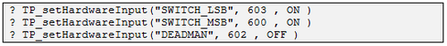
- Set the digital input numbers of the Deadman and Mode Selector switches:
- Define the type of teach pendant (2 options):

- Define the type of coordinate frame (2 options):

- Define whether a log file will be created and maintained (true or false):

- If a log file is enabled, set the maximum size of file:

A log file is created and filled until it reaches the maximum size. When filled, a second log file is created and filled to maximum size.
Once the second file is filled to capacity, the log overwrites the first log file. - Define the type of teach pendant keyboard. Currently only one type is available; the line should be as follows:

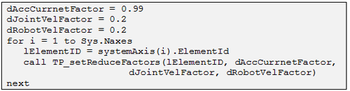
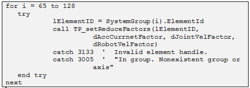
- For safety purposes, set values for reducing velocity, acceleration and current for each motion element (group and/or single axis).
Invoke the settings for each motion element ID, as shown here:
- Set the digital input numbers of the Deadman and Mode Selector switches:
- Save TP_INIT.PRG and send the file to the controller (right-click “Copy to Controller”).
- In the Controller File list, locate the file AUTOEXEC.PRG.
[Alternately, if using Configurator, use the file STARTPRG.PRG].
Select and drag the file from the Controller Files list to the PC File list.
Double-click to open AUTOEXEC.PRG for editing in the Terminal pane.
At the end of the program, add the line:

Save AUTOEXEC.PRG and send the file to the controller (right-click “Copy to Controller”). - Initialize the softMC and the TP. In the Terminal pane, enter the commands:

[Alternately, if using Configurator, enter the commands:].

- In the Message Log pane, check for the following message:


The softTP is now ready for operation.
Browser Setup
To set-up the IP address of the softMC on your softTP you will need to do the following (Note, all the snapshots below are from softTP screen):
- Strat softMC Scanner (from Desktop)
- Select network adapter
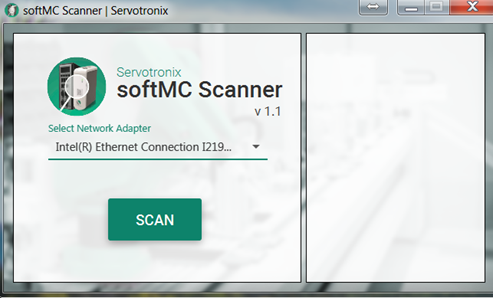
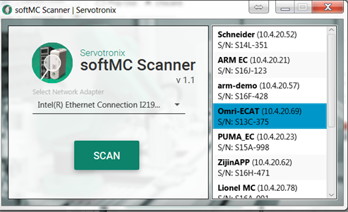
- Click on softMC in the list to open in browser and then set as homepage
- Go to firefox options (the menu is located right of the address bar):
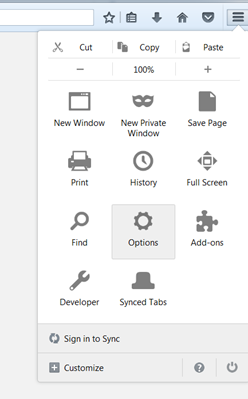
- Change the homepage to the softMC’s IP and close the window.


Appendix
This appendix describes alternative setups for using the TP Emulator software instead of the actual softTP.
TP Emulator Communicating with softMC
This configuration is useful for working with a real robotic system when an actual teach pendant is not available.
An HTML5 browser is used either on laptop or tablet.
|
|
It is extremely dangerous to work without safety switches. Maintain a safe distance (beyond the reach of the robotic arm) while working with robot. |
Hardware setup

Software Setup
To prefer the software for this configuration, refer to the section Software Setup, and do the following:
- Step 1: Java Runtime Engine
- Step 2: Java Web Server
- Step 3: softTP license
- Step 4: TP library of MC-BASIC files
- Step 5: TP_INIT.PRG file:
Do not define any I/Os.
Define the teach pendant and keyboard types as follows:

- In the browser, call the file emulator.html (instead of index.html).
For example: e.g., 10.4.20.148/emulator.html
TP Emulator Communicating with Virtual (Simulated) softMC
This configuration is useful for working with a completely simulated robotic system.
An HTML5 browser is used on either the same or a different PC.
Hardware Setup

Software Setup
To prefer the software for this configuration, refer to the section Software Setup, and do the following:
- Step 1: Java Runtime Engine
- Step 2: Java Web Server
- Step 3: softTP license
- Step 4: TP library of MC-BASIC files
- Step 5: TP_INIT.PRG file:
Do not define any I/Os.
Define the teach pendant and keyboard types as follows:

- In the browser, call the file emulator.html (instead of index.html).
For example: e.g., 10.4.20.148/emulator.html