Difference between revisions of "Multi-Axis Kinematics/zh-hans"
| Line 219: | Line 219: | ||
| | | | ||
[[Image:Axsystems;UserManual-1-Interpolation.png|caption|600px]]<br> | [[Image:Axsystems;UserManual-1-Interpolation.png|caption|600px]]<br> | ||
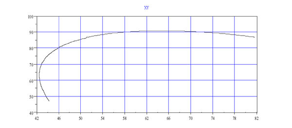
| − | + | 下图显示了在关节空间中看到的'''MOVES '''。 | |
| | | | ||
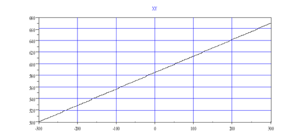
[[Image:Axsystems;UserManual-2-Interpolation.png|caption|600px]]<br> | [[Image:Axsystems;UserManual-2-Interpolation.png|caption|600px]]<br> | ||
| − | + | 下图显示了在世界空间中看到的'''MOVES '''。 | |
|- | |- | ||
| | | | ||
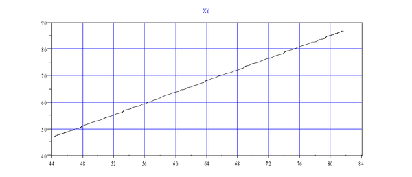
[[Image:Axsystems;UserManual-3-Interpolation.png|caption|600px]]<br> | [[Image:Axsystems;UserManual-3-Interpolation.png|caption|600px]]<br> | ||
| − | + | 下图显示了关节空间中显示的'''MOVES ''' | |
| | | | ||
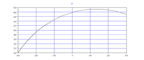
| − | [[Image:Axsystems;UserManual-4-Interpolation.png|caption|600px]] | + | 下图显示了世界空间中显示的'''MOVES '''<br> |
| − | + | [[Image:Axsystems;UserManual-4-Interpolation.png|caption|600px]] | |
|} | |} | ||
Revision as of 08:52, 17 May 2017
| 语言: | [[::Multi-Axis Kinematics|English]] • [[::Multi-Axis Kinematics/zh-hans|中文(简体)]] |
|---|
Contents
- 1 介绍
- 2 耦合
- 3 Points
- 4 Refer to
介绍
多个轴可以组合并移动。 有:
- 简单组((无模型,可以是相同类型或不同类型)
- 笛卡尔组(每个轴的作用被严格定义,例如:XYZ,XYZR,...)
- 机器人(应用特定机器人模型(SCARA,PUMA,...)
组是数据对象(运动元素),使我们能够将其轴同步移动。如果所有的轴都是相同类型(全部是线性轴或全部旋转轴),它们的速度,加速度和加加速度值可以组合起来(使用平方和的平方根),运动参数将具有物理意义。 我们称这些类型的组为homogeneous groups。
Non-homogeneous groups由旋转轴和线性轴两种轴组成。增加了一个特征来支持非同类型组速度的定义。 在设置中,声明旋转轴和线性轴。 系统确定它是线性还是旋转主导组。例如,在SCARA机器人中,有两个旋转轴用于第一和第二个关节,另一个旋转轴用于最后一个关节(旋转)。 只有一个线性轴(Z轴)。这种系统是旋转主导的。 另一个例子是XYZ-Roll系统。 这里,只有一个旋转轴(旋转)有两个线性(X和Y)轴和另一个线性(Z轴)。 在这种情况下,系统是线性主导的。 轴设置定义组的行为。每个轴必须声明是线性轴或旋转轴,通过设置 POSITIONROLLOVERENABLE 为线性轴(0)或旋转轴(1)。
在非同类型组中, 根据组的主导类型(参考: DOMINANCEMODE)总是给出联合插补运动(MOVE)命令速度。如果该组是线性优势的,速度(VCRUISE, VFINAL)为线性单位(mm / sec)。 在运动的准备阶段检查其他非线性轴。 这些轴的速度不能超过最大值。 如果是这样,总体(组)速度就会降低。
这个规则只有一个例外。这是当一个组运动只发出一个运动轴并且其他轴停止时。然后,给定速度的单位直接取决于该轴的单位。 例如,SCARA机器人的第三轴上具有运动,速度值以mm / sec为单位。
对于组内插补运动的加速度和加加速度值也是如此。
如果非同类型组中的设置不正确,即有不同类型的轴但是但所有轴的POSITIONROLLOVERENABLE都设置为相同的值。运动组仍然会运动,但是组中速度/加速度/加加速度值将不再具有物理意义。如果轴之间的数值显着不同,则系统可能有线。?
| NOTE | |
| 上述讨论仅适用于组的简单联合插值运动(请参阅Move or Circle)。 笛卡尔组中Moves和Circle使用Vtran和Vrot参数。 |
坐标系
世界坐标系
具有不同的世界和关节坐标使机器人运动学独一无二 。世界坐标通常被认为是应用程序的工作坐标。通常基于机器人基座的笛卡尔坐标系有一些其他的形式。
另外一种是在终端执行器(比如夹爪等)的方向添加另一组坐标。刚体在空间中的方位通常用三个角度描述。根据自由度的数量(电机用来驱动关节角度),它们可能不相等。在大多数情况下,世界空间坐标由其位置部分(X,XY或XYZ元组)给出。 一般来说,它可以是从球坐标到圆柱坐标的任何东西。 方向组件可以使用许多形式来描述方向。大多数使用的方向角坐标系是欧拉角:偏航,俯仰和滚转。理论上,欧拉角有12种不同的表现形式,根据大多数机器人模型中使用Z-Y-Z顺序的方向顺序。
关节坐标系
机器人的关节空间是一个相对简单的概念。关节坐标是唯一描述机器人相对于先前的位置的数字。 如果连接节段的关节是旋转的,则关节坐标为旋转角度。 如果是线性的,则关节坐标是线性位移(毫米)。
点数据类型
关节坐标的概念是一个n元组数。 每个数字表示特定关节的坐标。 世界坐标由描述每个不同世界空间表示的不同内置类型(XY,XYZ,XYZR)支持。 对于相同(或相同维度)的世界坐标,可以有不同的世界空间描述。 每个机器人都有其默认的世界空间类型。 不同的机器人可以具有相同的世界空间类型,只要它们具有相同数量的自由度(NDOF)。 例如,xy平台世界空间具有XY世界空间描述符。SCARA机器人有用于垂直运动的Z轴和用于定向的转动轴,使用由由X,Y,Z和转动或XYZR描述组成的世界坐标系。
不同的坐标系被实现为不同数据类型的变量。 通常,坐标系中的一个点被定义为点数据类型。 根据是否是关节空间或世界空间,点的子类型不同。 点数据类型有两个子类型: JOINT和LOCATION。两者都有一个世界空间描述符,可以区分相同的子类型。 世界空间坐标存储在变量中,定义为:
DIM A AS LOCATION OF XYZR
关节空间是:
DIM A AS JOINT OF XYZR
具有两个子类型(LOCATION和JOINT)和世界空间描述符(XY,XYZ,XYZR等)的点数据类型涵盖了所有可能的机器人空间变化。这些变量与机器人无关,可以在系统中未定义机器人的情况下使用。当它们与机器人或组的连接使用时,世界子类型必须相等。
该点可以使用所有可用的算术运算(+ - * /)作为数值数据类型进行操作。 操作被定义为逐个坐标操作。只有相同子类型和相同世界空间的点可以组合。
用于点常数的语法: 用方括号({})内的命令分隔的值列表表示点。 如果它之前是井号(#),它是一个位置:
DIM C AS LOCATION OF XYZR
C = #{0,0,0,0}

DIM I AS JOINT OF XYZR
I = {0,0,0,0}
用户单位
softMC可以让您自由地更改和选择不同的单位。机器人模型具有较小的灵活性。由于关节和世界空间之间的紧密关系,您必须以毫米或度数定义关节位置单位,以秒为单位定义所有时间单位,以便世界空间和关节间隔都是兼容单位。世界空间的单位自动设置为毫米-度-秒。
每个轴都有四个缩放因子: PFAC,VFAC, AFAC, and JFAC。这些将编码器计数和旋转计数转换为用户位置单位(英寸,毫米或圈)。它们还指定在位置求导中使用什么时间单位(VEL, ACC, JERK)。由于位置因子定义了计数和用户位置单位之间的比例,其余因子定义了毫秒和用户时间单位之间的比率。 通常有:
<axis>.pfac = <number of counts per user position units>
<axis>.vfac = pfac/1000 (if in seconds)
<axis>.afac = vfac/1000 (if in seconds)
<axis>.jfac = afac/1000 (if in seconds)
所有轴都设置完毕后,组包含这些轴。 所有轴上必须具有相同的用户单位。 设置组缩放因子 组没有位置因子! 相反, 使用每个轴的 PFAC。
MOVE g1 {1,2,3} vcruise = 10
目标坐标被给予每个轴,并且转换成使用每个轴的PFAC编码器/解析器计数。 VCRUISE与任何轴无关。 使用组因子, VFAC, AFAC和JFAC。 组速度以用户单位/秒表示。
要使系统单元正常工作, 请将每个轴的单位因子 (PFAC, VFAC, AFAC and JFAC)设置为毫米-度-秒并将组单位设置为秒:
<group>.vfac = 1/1000
<group>.afac = vfac/1000
<group>.jfac = afac/1000
耦合
在许多机器人应用中,机械结构引入轴之间的机械耦合。在这种情况下,两个或多个电机只移动一个关节。 因此,仅激活一个电机会导致两个轴(关节)的运动。有很多这样的机械设置的例子。通常当电机移动关节时,它们正在启动。 当电动移动第二关节置于第一关节之前时,第二关节通过第一和第二电机的运动而移动。这种应用的典型实例是移动机械手臂(PUMA)的电机通过链条或皮带移动机器人手臂。最后一个机器人部件上的差速齿轮传动从末端执行器移动最后一个电机(转动),第五和第六个电机在第六个和第六个电机上引入运动(Staubli RX系列)。
Staubli RX 手腕 – 对轴 a5 ,a6:
j6.pcmd = a6.pcmd – a5.pcmd
BOSCH – SCARA – 对轴 a3,a4:
j3.pcmd = a3.pcmd + 18.3*a4.pcmd.
PUMA – a2,a3 and a4:
j4.pcmd=a2.pcmd+a3.pcmd+a4.pcmd.
缩放和旋转:
j1 = 707.1*a1.pcmd + 707.1*a2.pcmd
j2 = 707.1*a1.pcmd + 707.1*a2.pcmd
正交校正:
j1 =10000*a1.pcmd
j2 = 2.91*a1.pcmd + 10000*a2.pcmd
组关节是softMC固件的标准配置,涵盖上面给出的耦合示例。
运动元素
softMC是一个多轴和多组系统。在许多方面,组和轴是相同的。例如,它们都具有以下属性: AMAX', VMAX, VCRUISE。另一个相同的方面是两者的运动。虽然运动命令有仅组(CIRCLE, MOVES) 或仅轴(JOG),但单独移动轴时,不可能移动包含相同轴的组,反之亦然。轴在组中有效。 ATTACH''DETACH的工作方式相同,当轴的组已经关联时,轴不能再关联。 因此,我们可以使用一个术语motion-element来表示轴和组。
有一些是仅属于轴或仅属于组的属性。例如DRIVEADDRESS是一个仅属于轴的属性。
MOVE包含两种不同的命令特性,Move-Group和Move-Axis。Move-Group将全部组一起移动。组内的所有轴在同一时间开始和结束运动。Move-Group保持在组和轴的运动学限制 (VELOCITY,ACCELERATION,JERK)。组的限制被执行并施加组运动上(集合,空间XY,XYZ)。轴限制仅与轴运动与整个组运动的比例成比例的执行。如果轴X向Y轴一半移动,则只能使用一半的极限值。运动的总时间是最慢轴完成运动所需的时间。这里,最慢的轴是具有最大路径/速度比的轴,并且不需要具有最小最大速度的轴(因为如果这样的轴没有运动,则不是最慢的轴)。另一方面,Move-Axis仅检查指定轴的极限,并且与使用该轴的任何组的极限无关。
分析器的准备可以额外减少运动参数。这是典型的短暂的运动,由于ACCELERATION和JERK的现有限制,给定的巡航速度无法达到。
关节
关节是虚拟轴。 无论从语言的角度看,还是耦合轴的物理运动,关节只给出一个轴的错觉,关节类似于轴,关节表示为J1,J2等
根据给定的耦合矩阵,每个关节实际上表示该组的一个或多个轴。如果组没有定义耦合矩阵,则关节是组中相同序数的轴作为关节索引的直接表示。 为了引入另一个术语,关节的"影轴"是组中与关节索引具有相同序数的轴。 例如,如果一组由轴A2,A3,A4组成,则关节J1的影轴为A2。
通常,所有关节属性都是影轴属性的直接表示(具有相同的值),与是否定义了耦合矩阵无关。唯一的例外是与关节位置相关的属性: PCMD, PFB, VCMD, VFB, CCMD, CFB, PMAX和PMIN,这些是每个关节独有的。
根据给定的耦合矩阵获得当前位置和速度。每次发出这些值的查询(PCMD, PFB,等)时都会计算它们。它们是只读的,不表示任何特定的内部变量。从组(?g1.PCMD)查询时,对称地具有相同的属性,根据耦合矩阵返回关节属性值的列表。 组运动的运动的目标位置(MOVE or CIRCLE)类似(耦合矩阵)处理。
另一方面,关节的位置限制(PMAX和PMIN) 被添加到关节中。 关节的位置限制和影轴的位置限制不相关,与是否定义耦合矩阵无关。当定义耦合矩阵(COUPLED = 1)时,总是使用关节位置限制。 在这种情况下,不会使用影轴限制。 这只适用于关节和组运动。单轴运动(例如,MOVE A1 100)仅受轴限制的限制,与耦合无关。
关节代表一组中的几个轴。 关节运动实际上是组运动:
Move-Group = Move-Joint
关节运动给出移动一个物理轴(MOVE J1 100)的错觉,尽管有几台电机可以在一起移动。根据指定的关节运动参数执行运动。 例如:
A1.Acc = 100
MOVE A1 50
类似于:
J1.Acc = 100
MOVE J1 50
Move-Joint模拟通过参数和物理运动移动单个关节来移动单个轴的行为。唯一的区别是几台电机正在移动而不是一个电机。关节移动时,检查每个组轴内的所有电机限位。关节运动是一组关节坐标与从影轴复制的组运动参数的组运动。下面的转换规则为真:
MOVE J1 10 <=> MOVE {10,0,0,0} abs = J1.abs vcruise = J1.vcruise acc = J1.acc
机器人模型
机器人被定义为具有特殊型号类型的组 (请参阅当前可用的机器人型号列表: robot_model_table)
例如:
COMMON SHARED scara AS GROUP AxNm = a1 AxNm = a2 AxNm = a3 AxNm = a4 Model = '''4'''
机器人设置
这将自动定义具有SCARA运动学模型的机器人。与仅需要使能轴的通用组相反,必须设置机器人参数并对其进行配置。 不同的机器人需要设置的参数不同。对SCARA机器人, 这些是:
- 使用所有标准运动学参数设置所有轴
- 定义转属性
- 设置整个组的所有用户单位因子: VFAC, AFAC, JFAC
- 设置每个机械臂链接的连杆长度和关节角度
- 设定通用组的运动学 (VELOCITY, ACCELERATION, JERK, etc.)
- 设定笛卡尔运动的运动学 (VTRAN,VROT, etc.)
只有在设置好所有这些并且成功执行CONFIGGROUP之后,机器人才能运动。否则返回错误,表示该组未配置。常规组(默认模型值1)与机器人之间的重要区别是执行CONFIGGROUP的必要性。 在机器人组中,机器人在配置之前不允许运动。
模型值自动定义默认机器人世界空间描述符。 对于模型4(SCARA),选择XYZR(x-y-z-roll)世界空间。
在有定义的机器人模型(模型> 1)的组中,关节和世界空间之间不是简单的转换。将“关节坐标转换为世界坐标是用TOCART来实现的,它将机器人和给定的关节坐标(位置变量)同时作为输入参数。其输出是与给定关节位置对应的世界坐标。
另一个方向更复杂。 通过TOJOINT 接收三个输入参数来实现:机器人,给定的笛卡尔点和配置标志。
配置标志用于在两个翻译功能之间进行选择。在大多数机器人模型中,对于相同的世界空间位置,有多个关节坐标描述。不同的机器人配置可以产生有不同关节空间值但是有相同的世界空间位置。不同的机器人配置不同,在 在SCARA中,只有两个配置:lefty(第二个关节坐标是负的)和righty(第二个关节坐标是正的)。
插补
对于有机器人型号(型号> 1)的组,还有一个额外的运动类型:MOVES。运动从起始位置到世界空间中给定的目标位置是一条直线。平直度与工作空间紧密相关。 相同的路径在笛卡尔工作空间(XYZ)中可以是直的,但在关节空间中弯曲,反之亦然。 MOVES 仅用于机器人类型的组,不能在通用组中使用。
直线运动是指在世界空间中是直线的运动。在没有机器人模型(模型= 1)的组中,使用MOVES生成的所有运动是关节空间中的直线运动。在通用的线性主导组中,它们的大多数轴是线性的。由于世界空间和关节空间是相同的, MOVES在关节空间和世界空间中执行一条直线。目标位置可以在世界和关节空间坐标中给出。运动与关节插值(MOVE)不同。 使不是用常规组中使用的关节空间运动学参数,而是使用速度,加速度和加加速度的世界空间参数。这些参数有两种形式:一种用于运动的平移部分,另一种用于旋转部分(方向)。
当世界空间具有位置和方向分量时,直线运动包括位置和方向上的插值。 因为这两个在本质上不同的对象,所以需要两个不同的参数:一个用于平移(纯位置插值): VELOCITYTRANS, ACCELERATIONTRANS, JERKTRANS; 另一个用于旋转(旋转插值): VELOCITYROT, ACCLERATIONROT, JERKROT. 这些参数仅用于笛卡尔插值(MOVES and CIRCLE)。这些参数对关节插值MOVE)没有影响,因为它不是世界空间插值。
两组参数定义了直线运动。 哪个参数是运动的主要因素取决于运动。 如果大部分运动都处于平移位置的变化,方向的变化要小得多,则平移部分被采用。 相反,旋转参数定义直线运动。
There are four commands to make point-to-point movement in robot groups. There are two commands to interpolate the motion (MOVE and MOVES) and two commands to define the target point (JOINT and LOCATION). The total combination of these gives four options.
| LOCATION target | JOINT target | |
| Cartesian-Interpolation | MOVES #{400,400,0,0} | MOVES {45,45,0,0} |
| Joint-Interpolation | MOVE #{400,400,0,0} | MOVE {45,45,0,0} |
Contouring
Contouring connects different motions by defining the final velocity for each movement. This way, the motion does not stop at the segment. It is continued with the next motion. This method is applicable in one-axis applications, but has several drawbacks that become more prominent in multi-axis applications:
- The angle between the movements' direction must be zero. Otherwise, a jump in velocity occurs.
- It is not possible to connect arc with linear segments without a jump in acceleration.
- You must calculate the achievable final velocities on each segment to stop after the last segment.
Working Envelope
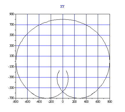
Robot working space is determined by the position limits of each joint. The working space (all reachable positions) is limited by the working envelope of the robot. From the outer side, it is limited by the arc made rotating the first joint with a fully stretched arm (j2.pcmd=0). This is the maximum radius of reachable points (RMAX). It is an internal value computed each time the robot is configured (CONFIGGROUP). Points given outside this radius are rejected with the error message, Point Too Far.
The other limit is the small circle with the radius (RMIN). This circle is obtained by rotating the first joint with a maximally-folded second joint (not more then 180 degrees). This radius is additionally enlarged by the robot's base size and the attached end-effector mechanism to prevent the robot from colliding with itself. The minimal working envelope radius (RMIN) is available to the user (contrary to RMAX). It is recommended that this value be set for each application according to the physical setup of the robot. If a point is given inside RMIN, an error message is returned. For example:
Program
 attach
 move {j1.pmin,j2.pmin,0,0}
 while ismoving
  sleep 1
 End While
 Print "Plotting the workspace"
 move {j1.pmin,0,0,0}
 move {j1.pmax,0,0,0}
 move {j1.pmax,j2.pmax,0,0}
 detach
End Program
Robot Configurations
In robot models, there are several joint points representing the same robot end-effector position for each location point. To uniquely select between different joint coordinates, there are configuration flags.
For SCARA kinematics, there is only one configuration flag available: the arm flag. It indicates either lefty (1) (j2.pcmd > 0) or righty (2) (j2.pcmd > 0). A value of 1 (lefty) means that the joint coordinates having a positive second joint are taken to represent the given location. The current configuration of the robot is returned by ARMFBK. The value can be 1 or 2, depending on the position feedback value of the second joint. ARMFBK determines the movement's target position. It can be automatic (0), lefty(1) or righty(2). When a movement with a Cartesian target position is given, the joint coordinates of the target position are selected according to ARMFBK. If it is zero (automatic), the current robot configuration is used (ARMFBK).
PUMA models traditionally use three configuration flags (arm,elbow and wrist – ACMD, ECMD, WCMD).
Another use of configuration flags is in the conversion function, TOJOINT. This function translates the given location point into joint point. It receives two arguments. The first is the location variable and the second is the configuration flag.
Points
A point is a data type used for storing a list of doubles in a variable. The main advantage of points is that you can directly call the whole vector without having to access every element of it. There are two subt-ypes of the point data type: LOCATION and JOINT. Using both point types in the same expression results in a type mismatch translation error. Type casting between point types requires the usage of special system functions TOJOINT and TOCART.
Declaration
A point must be declared before you can use it. The declaration of points is defined according to the type of robot (XYZR, XYZ, etc.). The softMC enables the declaration of point variables, which can be scalar or arrays. Point arrays may have up to 10 dimensions. Point variables are designed to hold a list of 2 to 10 double-type coordinates. A point variable is declared in relation to a robot type. Therefore, declaring a point variable must include the name of a valid robot type. The dimension of the point is the same as the dimension of the type of robot. The syntax is:
(COMMON SHARED|DIM {SHARED}) <variable_name> AS JOINT OF <robot_type>(COMMON SHARED|DIM {SHARED}) <variable_name> AS LOCATION OF <robot_type>
<robot_type> can be:
XYZR – Three cartesian axes + rollXY – two axes XY tableXYZ – three axes XYZ system
For example:
Common Shared JointXYZ As Joint Of XYZ
Common Shared JointXYZR As Joint Of XYZR
Common Shared LocXYZ As Location Of XYZ
JointXYZ = LocXYZ  --> Error – type mismatch
Variables
Two new variable types are defined for point variables in the translator: LOCATION and JOINT. For the translator, a point variable differs from any other type of variable (Long, Double, etc.) only by its type. A point variable is inserted to the expression tree as a variable leaf. The variable leaf retains data related to the point variable, including its context (system, program or local), its offset (taken from the symbol table), and its type (LOCATION or JOINT, also taken from the symbol table).
Declaration
When declaring a point variable, data corresponding to this variable is entered into the correct symbol table (depending on whether it is a system variable, a program variable, or a local variable). A point variable is defined in the symbol table by its name, its type (LOCATION or JOINT) and an offset of the data segment. Each offset of the data segment corresponds to the address of the point variable. The robot type string is sent to a special function that gives the robot-type value and the number of coordinates.
Constant Points
Constant points are location or joint vectors with an undefined robot type. The constant point’s subtype is defined by the shape of its brackets (#{ } for location, { } for joint). In the translator, each of these two vector types is considered an expression. Each expression-related command and manipulation (such as print commands, mathematical operators, etc.) can be applied for the joint and location vectors.
While executing a vector expression, each vector element is pushed separately into the stack as a double type expression (by executing the left side of the JOINT or LOCATION node). Long type vector elements are converted to double type expressions (in the coordinate node) after the execution of the expression at the right side of each coordinate node).
Execution of the right side of the JOINT or LOCATION node results in pushing the number of the vector elements into the stack (as a long type constant). The point’s subtype (determined by the shape of the vector’s brackets) is pushed to the stack (as a long type constant) by executing the third side of the JOINT/LOCATION node.
Vectors
Vectors are actually constant points, at which a list of 2 to 10 coordinates is written between curly brackets {}. In location vectors, the curly brackets are preceded by the # sign. A coordinate can be any type of expression (constant, variable, mathematical expression, function call, etc.) of long or double type. Long type coordinates are automatically converted to doubles. Unlike point variables, vectors are not related to robot types, and characterized merely by their size (number of coordinates).
{<expression_1>, …, <expression_n>} ‘ Joint vector
#{<expression_1>, …, <expression_n>} ‘ Location vector
Point variables and vectors appearing in the same expression must match in type (joint or location) and size.
Common Shared JointXYZ As Joint Of XYZ
JointXYZ = #{1.5, 2.8, 3} -->  Error – type mismatch
PRINT {20, 6.7, 23} + #{8.43, 2, 0} --> Error – type mismatch

JointXYZ = {2, 6} -->  Error – size mismatch
PRINT {20, 6.7, 23} - {5, 4, 22.9, 31} --> Error – size mismatch
Properties
Some group properties are points. There are several read-only properties of joint- (VELOCITYFEEDBACK, POSITIONCOMMAND, DEST_JOINT), and location-type (DEST, HERE, SETPOINT). There are also some location-type read-write properties, like TOOL, BASE, etc.
As in point variables, the robot type also characterizes point properties.Point properties appearing in expressions in a mixture with other points must match in type and robot type to point properties and variables, or in type and size to vectors.
Common Shared SCARA As Group Axnm = A1 Axnm = A2 Axnm = A3 Axnm = A4 Model = 4
Common Shared PointXYZR As Joint Of XYZR
Dim Shared PointXYZ As Joint Of XYZ
PointXYZR = SCARA.SetPoint --> Error – type mismatch (Setpoint returns a location)
PointXYZ = SCARA.VelocityFeedback --> Error – robot type mismatch
SCARA.Base = #{56.5, -104.7, -90.5} --> Error – size mismatch
Point Dimension
You do not define the size of the vector data type at the declaration of it, but you define the type of robot related to the point. This gives the point a dimension.
Point Assignment
Point assignment uses the following syntax:
<variable_name> = (<expr1>,<expr2>,<expr3>,…,<exprn>)() = #{} for location() = {} for joint
The expression can be a constant or other vector variable of the same robot type, but the size of the right side of the expression must equal the left side. If you try to assign a point with a point of other robot type, an error is received.
Single Coordinate Point Assignment
The syntax for assigning a single coordinate of a point is:
<variable_name>{<expression>} = <expression>
Point Query
The syntax for querying a point is:
?<variable_name>
Single Coordinate Point Query
The syntax for querying a single coordinate of a point:
?<variable_name>{<expression>}
Example 1
Common shared P1 as location of XYZR 'declaration of a vector (global)
P1 = #{1,2,3,4} 'assign the whole vector
P1 = #{1,2} 'return a translation error
?P1 'read the whole vector
?P1{2} 'read the second coordinate of the vector
Example 2
Common shared P2[5] as location XYZ 'declare a global array of vectors
P2[1] = #{1,2,3} 'assign the whole vector
P2[2] = #{5,2} 'return a translation error
?P2[1] 'read the whole vector
?P2[2]{2} 'read the second value of the vector
Operators
Like any other data type, you can use operators for points. The system only defines the equal operator (plus, minus, multiplication and division). Operations between points can only be performed between points of the same type and robot type (or size). All operations can also be performed between points and long or double type expressions.
Assignment
Point variables and read-write properties can be assigned by point variables, vectors and point properties compatible in type and size (or robot type).
Query
Point variables, properties and vectors return a value, so they can all be queried through printing or assignment into a compatible point variable or read-write property.
Common Shared SCARA As Group Axnm = A1 Axnm = A2 Axnm = A3 Axnm = A4 Model = 4
Common Shared PointVar1 As Joint Of XYZR
Dim Shared PointVar2 As Joint Of XYZ
Dim PointArr[4] As Joint Of XYZR
PointVar1 = PointArr[2]
PointVar2 = {23.4, 60, 42}
PointArr[1] = SCARA.PositionCommand
SCARA.Tool = #{10, 20,30, 0}
PRINT PointVar2, SCARA.Tool, {100.3, 20}
 --> {23.4 , 60 , 42} #{10 , 20 , 30 , 0} {100.3 , 20}
Plus
The point plus operator is used like any other data type. It adds each element of the first point with each element of the second point. The result is a point.
?{1,2}+{2,4}
--> {3,6}
Minus
The point minus operator is used like any other data type. It subtracts each element of the first point with each element of the second point. The result is a point.
?{1,2}-{2,4}
--> {-1,-2}
Multiplication
The point multiplication operator is used like any other data type. It multiplies each element of the first point with a number. You can only multiply a point with a single number (one-dimensional number). The result is a point.
?2*{2,4}
--> {4,8}
Division
The point division operator is used like any other data type. It divides each element of the first point with a number. You can only divide a point with a single number (one-dimensional number). The result is a point.
?{2,4}/2
--> {1,2}
?2/{2,4}
--> {1,0,5}
Compound (:)
Is an operator specific for points, which should be operated between two locations of the same size (or robot type).
? #{-56.5 , -104.7 , 89.5} : #{ 0.0, -104.7 , -0.5}
--> #{-56.5 , -209.4 , 89}
Limitations
MOD (modulus), ^ (power), logic and bitwise operators cannot be used for points.
Points cannot be used as condition in flow control statements and event definitions.
Points cannot be recorded.
Points in Functions
Point variables can be passed to functions and subroutines both by reference and by value. An entire array of points can also be passed (by reference) to a function or subroutine. On the other hand, point properties and vectors can only be passed by value. Points can also serve as return values of functions. However, the point type and size (or robot type) of an argument or a return value must match function declaration.
Passing By Value And Reference
A point can be passed by value and by reference like any other data type. For example:
Program
Dim p1 as joint of XYZR
Call Sub1(P1)
?p1
End program
Sub Sub1(X as joint of XYZR)
X = {1,2,3,4}
End Sub
This program assigns P1 to {1, 2, 3, 4} and prints {1, 2, 3, 4} as output. When a point is passed by reference or value, you can only pass a point of the same robot type to X. Otherwise, you receive a translation error.
Example 1
Program
Dim p1 as location of XYZR
Call Sub1(P1     --> TRANSLATION ERROR !!!
?p1
End program
Sub Sub1(X as location of XYZ)
X = #{1,2,3,4}
End Sub
Example 2
Program
Dim p1 as joint of XYZR
Call Sub1(P1)     --> TRANSLATION ERROR !!!
?p1
End program
Sub Sub1 (ByVal X as joint of XYZ)
X = {1,2,3,4}
End Sub
Returning Point From Function
A function can return a point variable like any other data type. For example:
Dim A as location of XYZR
Program
Move G1 MyFunc(1) vcruise=299
    --> this will be OK if G1 is of XYZR robot type.
End Program

Function MyFunc(i1 as long) as location of XYZR
MyFunc = #{1,2,3,4}
End Function
Motion Commands
Some motion commands use point nodal parameters when applied on groups. For example: CIRCLE, MOVE and MOVES.
Some nodal parameters can be assigned with both point types (LOCATION and JOINT), like CIRCLECENTER, CIRCLEPOINT and the target positions of MOVE and MOVES. Other nodal parameters can accept only location points, like TOOL, BASE, etc. Assign all nodal parameters with points compatible in robot type or size to the group.
Common Shared SCARA As Group Axnm = A1 Axnm = A2 Axnm = A3 Axnm = A4 Model = 4
Common Shared JointXYZ As Joint Of XYZ
MOVE SCARA JointXYZ    --> Error – robot type mismatch
CIRCLE SCARA Angle = 180 CircleCenter = #{350, 500, -80}
 --> Error – size mismatch
MOVES SCARA #{-22, 503.8, -8.3, 149} Base = SCARA.Dest_Joint
 --> Error – type mismatch
Point As An Expression
Points properties can be stored as a point or can be compared as a point. For example:
Dim A as Joint of XYZR
A = {1,2,3,4}
A = G1.Pcmd
A = G2.Pcmd --> returns a translation error if G2 is not of XYZR type.
Functions
The following functions are defined:
<XYZR location> = TOCart (<group>, <XYZR JOINT>)
<XYZR Joint> = ToJoint(<group>,<XYZR LOCATION>,<configuration-flag:integer>)
<double> distl(<location>,<location>) Distance between points (length).
<double> distr(<location>,<location>) Distance between points (angle).
Where for TOJOINT instruction the number and type of configuration flags depend on each robot type. Note that robot properties ARMCMD, ECMD, WCMD have all three values(0,1,2) where 0 is reserved for AUTO option. The configuration bits however have only two values (0,1).
for SCARA robot : Arm ( Bit 0): value = 0 - Lefty(armcd = 1)value = 1- Righty(armcmd = 2)
for PUMA robot : Arm ( Bit 0): value = 0 - Lefty(armcd = 1) value = 1 - Righty(armcmd = 2)
Elbow ( Bit 1):value = 0 - Below(ecmd = 1) value = 1 - Above(ecmd = 2)
Wrist ( Bit 2): value = 0 - Noflip (wcmd = 1) value = 1 - Flip (wcmd = 2)
for TRAVERSE-ARM robot: Arm ( Bit 0): value = 0 - Lefty(armcd = 1)value = 1 - Righty(armcmd = 2)
for DELTA, SCISSORS, … and other robots that have no configuration flags these fields are not used.
The configuration flag argument of the tojoint is defined as:
SAVE/LOAD
Each global variable can be stored in a file. The variable and its value are stored in same syntax as it is defined in the program. You can select a data-type to be stored. If a data-type is selected, the SAVE command stores only global variables of that data type. If file with same name already exist its extension is renamed to *.bak and new file is created. Loading the file overwrites the values of the saved global variables. You can save all the points related to some type of robot. For example:
SAVE file = "Myfile.prg" type = location robottype = xyzr
SAVE file = "Myfile.prg" type = all
LOAD Myfile.prg
