Difference between revisions of "Dynamic Models"
(Added DynamicModel = 2 of DELTA robot) |
|||
| (77 intermediate revisions by 5 users not shown) | |||
| Line 1: | Line 1: | ||
| + | This page gives an overview over all implemented dynamic models. | ||
| + | | ||
| + | |||
| + | '''General considerations''' | ||
| + | |||
| + | *Friction is handled on axis basis. The parameters for friction, [[MC-Basic:axis.COULOMBFRICTION|COULOMBFRICTION]] and [[MC-Basic:axis.VISCOUSFRICTION|VISCOUSFRICTION]], are set for each axis separately. | ||
| + | *Torque (Force) is always expressed in '''[Nm]''' ([N]) | ||
| + | *The dynamic model number is the value of [[MC-Basic:element.DYNAMICMODEL|<element>.DYNAMICMODEL]] | ||
| + | *The property numbers are the indexes of [[MC-Basic:element.DYNAMICPARAMETER|<element>.DYNAMICPARAMETER[<number>]]] | ||
| + | |||
| + | | ||
| + | |||
== Rotational Axes == | == Rotational Axes == | ||
=== Dynamic Model 1 - simple rotary axis === | === Dynamic Model 1 - simple rotary axis === | ||
| − | {|border="1" width="80%" | + | |
| − | !width="100"|Number | + | {| border="1" width="80%" |
| − | !width="250"|Parameter | + | |- |
| − | !Comments | + | ! width="100" | Number |
| + | ! width="250" | Parameter | ||
| + | ! Comments | ||
| + | |- | ||
| + | | 1 | ||
| + | | <math>I</math> | ||
| + | | Total moment of inertia around the rotation axis of the moved part | ||
| + | |} | ||
| + | |||
| + | ;Model equation | ||
| + | :<math>T = (I + I_{payload}) \cdot acc</math> | ||
| + | |||
| + | | ||
| + | |||
| + | === Dynamic Model 2 - horizontal crank-arm axis === | ||
| + | |||
| + | [[File:Axystems;Motion Dynamics - Horizontal Crank-Arm Axis.png|thumb|Horizontal crank-arm axis]] | ||
| + | |||
| + | {| border="1" width="80%" | ||
| + | |- | ||
| + | ! width="100" | Number | ||
| + | ! width="250" | Parameter | ||
| + | ! Comments | ||
| + | |- | ||
| + | | 1 | ||
| + | | <math>I</math> | ||
| + | | Total moment of inertia around the rotation axis of the moved part | ||
| + | |- | ||
| + | | 2 | ||
| + | | <math>L^2</math> | ||
| + | | Square of length of crank arm (axis to payload) | ||
| + | |} | ||
| + | |||
| + | ;Model equation | ||
| + | :<math>T = (I + I_{payload} + L^2 \cdot M_{payload}) \cdot acc</math> | ||
| + | |||
| + | | ||
| + | |||
| + | === Dynamic Model 3 - vertical crank-arm axis === | ||
| + | |||
| + | [[File:Axystems;Motion Dynamics - Vertical Crank-Arm Axis.png|thumb|Vertical crank-arm axis]] | ||
| + | |||
| + | {| border="1" width="80%" | ||
| + | |- | ||
| + | ! width="100" | Number | ||
| + | ! width="250" | Parameter | ||
| + | ! Comments | ||
| + | |- | ||
| + | | 1 | ||
| + | | <math>I</math> | ||
| + | | Total moment of inertia around the rotation axis of the moved part | ||
| + | |- | ||
| + | | 2 | ||
| + | | <math>L^2</math> | ||
| + | | Square of length of crank arm (axis to payload) | ||
| + | |- | ||
| + | | 3 | ||
| + | | <math>M \cdot g \cdot A</math> | ||
| + | | Mass (without payload) * Gravity * Distance to center of mass | ||
|- | |- | ||
| − | | | + | | 4 |
| − | |<math> | + | | <math>g \cdot L</math> |
| − | | | + | | Gravity * Distance to Payload |
|} | |} | ||
| + | |||
| + | ;Model equation | ||
| + | :<math>T = (I + I_{payload} + L^2 \cdot M_{payload}) \cdot acc - (M \cdot g \cdot A + M_{payload} \cdot g \cdot L) \cdot \sin(pos)</math> | ||
== Linear Axes == | == Linear Axes == | ||
=== Dynamic Model 1 - horizontal axis === | === Dynamic Model 1 - horizontal axis === | ||
| − | {|border="1" width="80%" | + | |
| − | !width="100"|Number | + | [[File:Axystems;Motion Dynamics - Horizontal Axis.png|thumb|Horizontal linear axis]] |
| − | !width="250"|Parameter | + | |
| − | !Comments | + | {| border="1" width="80%" |
| + | |- | ||
| + | ! width="100" | Number | ||
| + | ! width="250" | Parameter | ||
| + | ! Comments | ||
|- | |- | ||
| − | |1 | + | | 1 |
| − | |<math>M</math> | + | | <math>M</math> |
| − | |Total mass of the moved part. | + | | Total mass of the moved part. |
|} | |} | ||
| + | |||
| + | ;Model equation | ||
| + | :<math>T = (M + M_{payload}) \cdot acc</math> | ||
| + | |||
| + | | ||
=== Dynamic Model 2 - vertical or tilted axis === | === Dynamic Model 2 - vertical or tilted axis === | ||
| − | {|border="1" width="80%" | + | |
| − | + | [[File:Axystems;Motion Dynamics - Vertical Axis.png|thumb|Vertical linear axis]] | |
| − | + | ||
| − | + | {| border="1" width="80%" | |
|- | |- | ||
| − | | | + | ! width="100" | Number |
| − | | | + | ! width="250" | Parameter |
| − | + | ! Comments | |
|- | |- | ||
| − | | | + | | 1 |
| − | |<math>M | + | | <math>M</math> |
| − | | | + | | Total mass of the moved part. |
|- | |- | ||
| − | |3 | + | | 2 |
| − | |<math>g \cdot \cos(\alpha)</math> | + | | <math>M \cdot g \cdot \cos(\alpha)</math> |
| − | |Gravity coefficient used to consider payload mass. ('''g = 9.80665''') | + | | Constant force due to gravity. |
| + | |- | ||
| + | | 3 | ||
| + | | <math>g \cdot \cos(\alpha)</math> | ||
| + | | Gravity coefficient used to consider payload mass. ('''g = 9.80665''') | ||
|} | |} | ||
| + | |||
| + | ;Model equation | ||
| + | :<math>T = (M + M_{payload}) \cdot acc + M \cdot g \cdot \cos(\alpha) + M_{payload} \cdot g \cdot \cos(\alpha)</math> | ||
| + | |||
| + | | ||
| + | |||
| + | === Dynamic Model 3 - vertical axis with a spring === | ||
| + | |||
| + | [[File:Axystems;Motion Dynamics - Vertical Axis with spring.png|thumb|Vertical linear axis with a spring]] | ||
| + | |||
| + | {| border="1" width="80%" | ||
| + | |- | ||
| + | ! width="100" | Number | ||
| + | ! width="250" | Parameter | ||
| + | ! Comments | ||
| + | |- | ||
| + | | 1 | ||
| + | | <math>M</math> | ||
| + | | Total mass of the moved part. [kg] | ||
| + | |- | ||
| + | | 2 | ||
| + | | <math>K</math> | ||
| + | | The stiffness constant of the spring. [kg/s^2] | ||
| + | |- | ||
| + | | 3 | ||
| + | | <math>K \cdot X_{0}</math> | ||
| + | | The stiffness constant times the relaxation position of the spring. [kg*m/s^2] | ||
| + | |} | ||
| + | |||
| + | ;Model equation | ||
| + | :<math>T = (M + M_{payload}) \cdot (acc + g) + K\cdot (X-X_{0})</math> | ||
== Traverse Arm Robots == | == Traverse Arm Robots == | ||
| + | |||
=== Dynamic Model 1 === | === Dynamic Model 1 === | ||
| − | {|border="1" width="80%" | + | |
| − | !width="100"|Number | + | [[File:Inverse dynamic model for Traverse Arm kinematics - Definitions.png|thumb|Traverse Arm robot]] |
| − | !width="250"|Parameter | + | |
| − | !Comments | + | {| border="1" width="80%" |
| + | |- | ||
| + | ! width="100" | Number | ||
| + | ! width="250" | Parameter | ||
| + | ! Comments | ||
|- | |- | ||
| − | |1 | + | | 1 |
| − | |<math>M_1 + M_2</math> | + | | <math>M_1 + M_2</math> |
|- | |- | ||
| − | |2 | + | | 2 |
| − | |<math>A_2 \cdot M_2</math> | + | | <math>A_2 \cdot M_2</math> |
|- | |- | ||
| − | |3 | + | | 3 |
| − | |<math>A_2^2 \cdot M_2 + I_2</math> | + | | <math>A_2^2 \cdot M_2 + I_2</math> |
|- | |- | ||
| − | |4 | + | | 4 |
| − | |<math>M_3</math> | + | | <math>M_3</math> |
|- | |- | ||
| − | |5 | + | | 5 |
| − | |<math>g \cdot M_3</math> | + | | <math>g \cdot M_3</math> |
|- | |- | ||
| − | |6 | + | | 6 |
| − | |<math>I_4</math> | + | | <math>I_4</math> |
| + | |- | ||
| + | | 7 | ||
| + | | <math>J_4</math> | ||
|} | |} | ||
| + | |||
| + | | ||
| + | |||
| + | | ||
| + | |||
| + | | ||
| + | |||
| + | | ||
| + | |||
| + | | ||
| + | |||
| + | | ||
| + | |||
| + | | ||
| + | |||
| + | | ||
| + | |||
| + | | ||
| + | |||
| + | | ||
| + | |||
| + | | ||
| + | |||
| + | | ||
== Scara Robots == | == Scara Robots == | ||
| + | |||
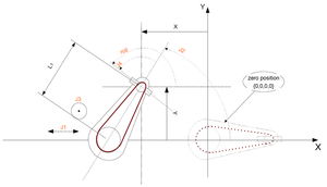
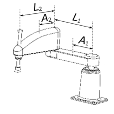
| + | [[File:scara with definitions.png|thumb|right|upright|scara robot]] [[File:moment of inertia.png|thumb|right|upright|Robot link moment of inertia is relative to it's center of mass]] [[File:reflected moment of inertia.png|thumb|right|upright|Rotor moment of inertia is reflected to gearbox output shaft]] | ||
| + | |||
| + | The dynamic equations of the robot are expressed at the outputs of the gearboxes attached to the actuation motors. Therefore, the torques, joint positions, velocities, and accelerations are those of the gearbox output shafts. | ||
| + | |||
| + | In the following models, the variable <math>M_i</math> for <math>i=1,...,3</math> is the mass of link <math>i</math>. Link <math>3</math> is a ball screw. The variable <math>p</math> is the lead of the ball screw, i.e. the linear distance traveled for each complete turn of the screw. The internal units of <math>p</math> are [mm/deg], while its user units are [m/rad]. | ||
| + | |||
| + | The variables <math>L_1</math> and <math>L_2</math> are the lengths of links <math>1</math> and <math>2</math>. The variables <math>A_1</math> and <math>A_2</math> are respectively the distances of the exes of joints <math>1</math> and <math>2</math> to the centers of mass of links <math>1</math> and <math>2</math>. | ||
| + | |||
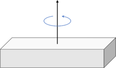
| + | The variable <math>I_i</math> for <math>i=1,...,3</math> is the moment of inertia of link <math>i</math>, relative to a reference frame attached to the link's center of mass, and about the link's axis of rotation. | ||
| + | |||
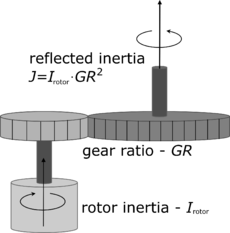
| + | Additionally, <math>J_i</math> for <math>i=1,...,4</math> is the moment of inertia of rotor <math>i</math>, reflected to the gearbox output shaft as follows. Let <math>I_{rotor,i}</math> be the moment of inertia of rotor <math>i</math> relative to a reference frame attached to the rotor's center of mass, about the rotor's axis of rotation. Let <math>GR_i</math> be the gear ratio of the gearbox or pulley system, then <math>J_i=I_{rotor,i} GR_i^2</math>. | ||
| + | |||
| + | The variables <math>M_0</math> and <math>I_0</math> are respectively the payload mass and payload moment of inertia relative to its center of mass. If no object or gripper is attached to the robot, the value of these variables is zero. | ||
| + | |||
| + | | ||
=== Dynamic Model 1 === | === Dynamic Model 1 === | ||
| − | {|border="1" width="80%" | + | |
| − | !width="100"|Number | + | For non-coupled SCARA robots (axis 3 and 4 are not coupled) and for concentric payloads (concentric with axis 4). |
| − | !width="250"|Parameter | + | |
| − | !Comments | + | {| border="1" width="80%" |
| + | |- | ||
| + | ! width="100" | Number | ||
| + | ! width="250" | Parameter | ||
| + | ! Comments | ||
| + | |- | ||
| + | | 1 | ||
| + | | <math>A_1^2 M_1+L_1^2 (M_2+M_3+M_0) + I_1 + J_1</math> | ||
| + | | kg*m<sup>2</sup> | ||
| + | |- | ||
| + | | 2 | ||
| + | | <math>A_2^2 M_2 +L_2^2 (M_3+M_0)+ I_2</math> | ||
| + | | kg*m<sup>2</sup> | ||
| + | |- | ||
| + | | 3 | ||
| + | | <math>J_2</math> | ||
| + | | kg*m<sup>2</sup> | ||
| + | |- | ||
| + | | 4 | ||
| + | | <math>L_1 A_2 M_2 + L_1 L_2(M_3+M_0)</math> | ||
| + | | kg*m<sup>2</sup> | ||
| + | |- | ||
| + | | 5 | ||
| + | | <math>M_3+M_0+J_3</math> | ||
| + | | kg | ||
| + | |- | ||
| + | | 6 | ||
| + | | <math>g (M_3+M_0)</math> | ||
| + | | kg*m/sec<sup>2</sup> | ||
|- | |- | ||
| − | | | + | | 7 |
| − | |<math> | + | | <math>I_3+I_0</math> |
| + | | kg*m<sup>2</sup> | ||
|- | |- | ||
| − | | | + | | 8 |
| − | |<math> | + | | <math>J_4</math> |
| + | | kg*m<sup>2</sup> | ||
| + | |} | ||
| + | |||
| + | | ||
| + | |||
| + | | ||
| + | |||
| + | | ||
| + | |||
| + | === Dynamic Model 2 === | ||
| + | |||
| + | For coupled SCARA robots (axis 3 and 4 are coupled) and for concentric payloads (concentric with axis 4). | ||
| + | |||
| + | {| border="1" width="80%" | ||
|- | |- | ||
| − | | | + | ! width="100" | Number |
| − | | | + | ! width="250" | Parameter |
| + | ! Comments | ||
|- | |- | ||
| − | | | + | | 9 |
| − | |<math>L_1 | + | | <math>A_1^2 M_1+L_1^2 (M_2+M_3+M_0) + I_1 + J_1</math> |
| + | | kg*m<sup>2</sup> | ||
|- | |- | ||
| − | | | + | | 10 |
| − | |<math>M_3</math> | + | | <math>A_2^2 M_2 +L_2^2 (M_3+M_0)+ I_2</math> |
| + | | kg*m<sup>2</sup> | ||
|- | |- | ||
| − | | | + | | 11 |
| − | |<math> | + | | <math>L_1 A_2 M_2 + L_1 L_2(M_3+M_0)</math> |
| + | | kg*m<sup>2</sup> | ||
|- | |- | ||
| − | | | + | | 12 |
| − | |<math> | + | | <math>M_3+M_0</math> |
| + | | kg | ||
|- | |- | ||
| − | | | + | | 13 |
| − | |<math>J_4</math> | + | | <math>I_3+I_0</math> |
| + | | kg*m<sup>2</sup> | ||
| + | |- | ||
| + | | 14 | ||
| + | | <math>J_2</math> | ||
| + | | kg*m<sup>2</sup> | ||
| + | |- | ||
| + | | 15 | ||
| + | | <math>J_3</math> | ||
| + | | kg | ||
| + | |- | ||
| + | | 16 | ||
| + | | <math>(M_3+M_0)p^2 + J_4</math> | ||
| + | | kg*m<sup>2</sup> | ||
|} | |} | ||
| + | |||
| + | | ||
| + | |||
| + | The payload parameters for Dynamic Model 1 and Dynamic Model 2 are: | ||
| + | |||
| + | {| border="1" width="80%" | ||
| + | |- | ||
| + | ! width="100" | Number | ||
| + | ! width="250" | Parameter | ||
| + | ! Comments | ||
| + | |- | ||
| + | | 1 | ||
| + | | payloadMass | ||
| + | | <math>M_0 </math>, the mass of the payload | ||
| + | |- | ||
| + | | 2 | ||
| + | | payloadInertia | ||
| + | | <math>I_0 </math>, the payload's moment of inertia relative to its center of mass | ||
| + | |} | ||
| + | |||
| + | | ||
| + | |||
| + | | ||
| + | |||
| + | | ||
| + | |||
| + | | ||
| + | |||
| + | | ||
| + | |||
| + | === Dynamic Model 3 === | ||
| + | |||
| + | For coupled SCARA robots (axis 3 and 4 are coupled) and for non-concentric payloads (the payload center of mass is not located along axis 4, and is located on the x-axis of the tool flange, which is defined by the zero position of axis 4).<br/> The dynamic parameters are the same as model 2, except for parameter No. 13. | ||
| + | |||
| + | The payload parameters are: | ||
| + | |||
| + | {| border="1" width="80%" | ||
| + | |- | ||
| + | ! width="100" | Number | ||
| + | ! width="250" | Parameter | ||
| + | ! Comments | ||
| + | |- | ||
| + | | 1 | ||
| + | | payloadMass | ||
| + | | <math>M_0</math>, the mass of the payload | ||
| + | |- | ||
| + | | 2 | ||
| + | | payloadInertia | ||
| + | | <math>I_0</math>, the payload's moment of inertia relative to its center of mass | ||
| + | |- | ||
| + | | 3 | ||
| + | | payloadLx | ||
| + | | the distance <math>L_{0x}</math> [m] to the center of mass from the 4th axis in the x direction | ||
| + | |- | ||
| + | | 13 | ||
| + | | <math>I_3+I_0+M_0 L_{0x}^2</math> | ||
| + | | [kg*m<sup>2</sup>], includes the additional term <math>M_0 L_{0x}^2</math> in accordance with the parallel axis theorem | ||
| + | |} | ||
| + | |||
| + | When using identification with this model, all of the payload parameters can be found. | ||
| + | |||
| + | | ||
| + | |||
| + | === Dynamic Model 4 === | ||
| + | |||
| + | Same as Dynamic Model 3.<br/> This model is used in identification process in order to identify the '''payloadMass''' parameter only, by moving only joint number 3. | ||
| + | |||
| + | | ||
| + | |||
| + | === Dynamic Model 5 === | ||
| + | |||
| + | Same as Dynamic Model 3.<br/> This model is used in identification process in order to identify the '''payloadInertia''' and '''payloadLx''' parameters, by moving only joint number 4 and very small movements in joints 1 and 2. | ||
== Delta Robots == | == Delta Robots == | ||
| + | |||
| + | |||
| + | === Dynamic Model 1 === | ||
| + | |||
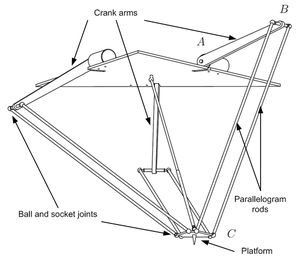
| + | Dynamic model of 3 DOF DELTA robot. | ||
| + | |||
| + | [[File:Control;Rod forces model for Delta kinematics - Introduction.png|thumb|Delta robot]] | ||
| + | |||
| + | {| border="1" width="80%" | ||
| + | |- | ||
| + | ! width="100" | Number | ||
| + | ! width="250" | Parameter | ||
| + | ! Comments | ||
| + | |- | ||
| + | | 1 | ||
| + | | <math>\Theta_{AB}</math> | ||
| + | | kg*m<sup>2</sup> | ||
| + | |- | ||
| + | | 2 | ||
| + | | <math>g \cdot L_{AB} \cdot M_{AB}</math> | ||
| + | | kg*m<sup>2</sup>/sec<sup>2</sup> | ||
| + | |- | ||
| + | | 3 | ||
| + | | <math>M_{BC}</math> | ||
| + | | kg | ||
| + | |- | ||
| + | | 4 | ||
| + | | <math>\Theta_{BC}</math> | ||
| + | | kg*m<sup>2</sup> | ||
| + | |- | ||
| + | | 5 | ||
| + | | <math>M_P</math> | ||
| + | | kg | ||
| + | |- | ||
| + | | 6 | ||
| + | | <math>M_T</math> | ||
| + | | kg | ||
| + | |- | ||
| + | | 7 | ||
| + | | <math>\Theta_T</math> | ||
| + | | kg*m<sup>2</sup> | ||
| + | |- | ||
| + | | 8 | ||
| + | | <math>\Theta_{T\phi}</math> | ||
| + | | kg*m<sup>2</sup> | ||
| + | |- | ||
| + | | 9 | ||
| + | | <math>L_{TO}</math> | ||
| + | | m | ||
| + | |- | ||
| + | | 10 | ||
| + | | <math>L_{TP}</math> | ||
| + | | m | ||
| + | |- | ||
| + | | 11 | ||
| + | | <math>D</math> | ||
| + | |- | ||
| + | | 12 | ||
| + | | <math>C_r</math> | ||
| + | |- | ||
| + | | 13 | ||
| + | | <math>Fr_{max}</math> | ||
| + | |- | ||
| + | | 14 | ||
| + | | <math>R_{ext}</math> | ||
| + | |} | ||
| + | |||
| + | | ||
| + | |||
| + | === Dynamic Model 2 === | ||
| + | |||
| + | Dynamic model of 4 DOF DELTA robot, with rotary 4th axis. The basic parameters are identical to those of DynamicModel = 1, with the calculation of the additional parameters of axis 4. The assumption is dynamic decoupling of the first three axes from the 4th axis. | ||
| + | |||
| + | | ||
| + | |||
| + | == Puma Robots == | ||
=== Dynamic Model 1 === | === Dynamic Model 1 === | ||
| − | {|border="1" width="80%" | + | |
| − | !width="100"|Number | + | [[File:puma.PNG|thumb|Puma robot]] |
| − | !width="250"|Parameter | + | |
| − | !Comments | + | Description: |
| + | |||
| + | : | ||
| + | :*<math>g </math> - Gravity constant | ||
| + | :*<math>m_{i} </math> - Mass of the i<sup>th</sup> link | ||
| + | :*<math>a_{i} </math> - length of the common normal between the i<sup>th</sup> and i<sup>th+1</sup> joints | ||
| + | :*<math>d_{i} </math> - offset along z axis between the i<sup>th</sup> and i<sup>th+1</sup> joints | ||
| + | :*<math>l_{i} </math> - The distance from the i<sup>th</sup> joint to the center of mass of the i<sup>th</sup> link | ||
| + | |||
| + | {| border="1" width="80%" | ||
| + | |- | ||
| + | ! width="100" | Number | ||
| + | ! width="250" | Parameter | ||
| + | ! Comments | ||
| + | |- | ||
| + | | 1 | ||
| + | | <math>I_{1} = I_{1,zz}+m_{1}*l_{1,y}^2 +m_{2}*d_{2}^2+(m_{4}+m_{5}+m_{6})*a_{3}^2+m_{2}*l_{2,z}^2+</math><br/> <math>(m_{3}+m_{4}+m_{5}+m_{6})*(d_{2}+d_{3})^2+I_{2,xx}+I_{3,yy}+2*m_{2}*d_{2}*l_{2,z}+m_{2}*l_{2,y}^2+m_{3}*l_{3,z}^2+2*m_{3}*(d_{2}+d_{3})*l_{3,z}+I_{4,zz}+I_{4,yy}+I_{6,zz}</math> | ||
| + | | kg*m^2 | ||
|- | |- | ||
| − | | | + | | 2 |
| − | |<math> | + | | <math>I_{2} = I_{2,zz}+m_{2}*(l_{2,x}^2+l_{2,y}^2)+(m_{3}+m_{4}+m_{5}+m_{6}*a_{2}^2</math> |
| + | | kg*m^2 | ||
|- | |- | ||
| − | | | + | | 3 |
| − | |<math> | + | | <math>I_{3} = -I_{2,xx}+I_{2,yy}+(m_{3}+m_{4}+m_{5}+m_{6})*a_{2}^2+m_{2}*l_{2,x}^2-m_{2}*l_{2,y}^2</math> |
| + | | kg*m^2 | ||
|- | |- | ||
| − | | | + | | 4 |
| − | |<math> | + | | <math>I_{4} = m_{2}*l_{2,x}*(d_{2}+l_{2,z})+m_{3}*a_{2}*l_{3,z}+(m_{3}+m_{4}+m_{5}+m_{6})*a_{2}*(d_{2}+d_{3})</math> |
| + | | kg*m^2 | ||
|- | |- | ||
| − | | | + | | 5 |
| − | |<math> | + | | <math>I_{5} = -m_{3}*a_{2}*l_{3,y}+(m_{4}+m_{5}+m_{6})*a_{2}*d_{4}+m_{4}*a_{2}*l_{4,z}</math> |
| + | | kg*m^2 | ||
|- | |- | ||
| − | | | + | | 6 |
| − | |<math> | + | | <math>I_{6} = I_{3,zz}+m_{3}*l_{3,y}^2+m_{4}*a_{3}^2+m_{4}*(d_{4}+l_{4,z})^2+I_{4,yy}+m_{5}*a_{3}^2+m_{5}*d_{4}^2+I_{5,zz}+m_{6}*a_{3}^2+m_{6}*d_{4}^2+m_{6}*l_{6,z}^2+I_{6,xx}</math> |
| + | | kg*m^2 | ||
|- | |- | ||
| − | | | + | | 7 |
| − | |<math> | + | | <math>I_{7} = m_{3}*l_{3,y}^2+I_{3,xx}-I_{3,yy}+m_{4}*l_{4,z}^2+2*m_{4}*d_{4}*l_{4,z}+(m_{4}+m_{5}+m_{6})*(d_{4}^2-a_{3}^2)+I_{4,yy}-I_{4,yy}+I_{5,zz}-I_{5,yy}+m_{6}*l_{6,z}^2-I_{6,zz}+I_{6,xx}</math> |
| + | | kg*m^2 | ||
|- | |- | ||
| − | | | + | | 8 |
| − | |<math> | + | | <math>I_{8} = -m_{4}*(d_{2}+d_{3})*(d_{4}+l_{4,z})-(m_{3}+m_{6})*(d_{2}+d_{3})*d_{4}+m_{3}*l_{3,y}*l_{3,z}+m_{3}*(d_{2}+d_{3})*l_{3,y}</math> |
| + | | kg*m^2 | ||
|- | |- | ||
| − | | | + | | 9 |
| − | |<math> | + | | <math>I_{9} = m_{2}*l_{2,y}*(d_{2}+l_{2,z})</math> |
| + | | kg*m^2 | ||
|- | |- | ||
| − | | | + | | 10 |
| − | |<math> | + | | <math>I_{10} = 2*m_{4}*a_{5}*l_{4,z}+2*(m_{4}+m_{5}+m_{6})*a_{3}*d_{4}</math> |
| + | | kg*m^2 | ||
|- | |- | ||
| − | | | + | | 11 |
| − | |<math> | + | | <math>I_{11} = -2*m_{2}*l_{2,x}*l_{2,y}</math> |
| + | | kg*m^2 | ||
|- | |- | ||
| − | | | + | | 12 |
| − | |<math> | + | | <math>I_{12} = (m_{4}+m_{5}+m_{6})*a_{2}*a_{3}</math> |
| + | | kg*m^2 | ||
|- | |- | ||
| − | | | + | | 13 |
| − | |<math> | + | | <math>I_{13} = (m_{4}+m_{5}+m_{6})*a_{3}*(d_{2}+d_{3})</math> |
| + | | kg*m^2 | ||
|- | |- | ||
| − | | | + | | 14 |
| − | |<math> | + | | <math>I_{14} = I_{4,zz}+I_{5,yy}+I_{6,zz}</math> |
| + | | kg*m^2 | ||
|- | |- | ||
| − | | | + | | 15 |
| − | |<math> | + | | <math>I_{15} = m_{6}*d_{4}*l_{6,z}</math> |
| + | | kg*m^2 | ||
| + | |- | ||
| + | | 16 | ||
| + | | <math>I_{16} = m_{6}*a_{2}*l_{6,z}</math> | ||
| + | | kg*m^2 | ||
| + | |- | ||
| + | | 17 | ||
| + | | <math>I_{17} = I_{5,zz}+I_{6,xx}+m_{6}*l_{6,z}^2</math> | ||
| + | | kg*m^2 | ||
| + | |- | ||
| + | | 18 | ||
| + | | <math>I_{18} = m_{6}*(d_{2}+d_{3})*l_{6,z}</math> | ||
| + | | kg*m^2 | ||
| + | |- | ||
| + | | 19 | ||
| + | | <math>I_{19} = I_{4,yy}-I_{4,xx}+I_{5,zz}-i_{5,yy}+m_{6}*l_{6,z}^2+I_{6,xx}-I_{6,zz}</math> | ||
| + | | kg*m^2 | ||
| + | |- | ||
| + | | 20 | ||
| + | | <math>I_{20} = I_{5,yy}-I_{5,xx}-m_{6}*l_{6,z}^2+I_{6,zz}-I_{6,xx}</math> | ||
| + | | kg*m^2 | ||
| + | |- | ||
| + | | 21 | ||
| + | | <math>I_{21} = I_{4,xx}-I_{4,yy}+I_{5,xx}-I_{5,zz}</math> | ||
| + | | kg*m^2 | ||
| + | |- | ||
| + | | 22 | ||
| + | | <math>I_{22} = m_{6}*a_{3}*l_{6,z}</math> | ||
| + | | kg*m^2 | ||
| + | |- | ||
| + | | 23 | ||
| + | | <math>I_{23} = I_{6,zz}</math> | ||
| + | | kg*m^2 | ||
|} | |} | ||
| + | === Dynamic Model 2 - Gravity === | ||
| + | |||
| + | This dynamic model is for cases where the robot moves very slowly.<br/> In such cases, the accelerations and velocities of the joints of the robot have little effect on the joints torques. The joints torques are mainly affected by gravity and friction.<br/> This model includes only the gravity and friction part of the PUMA robot dynamic model. | ||
| + | |||
| + | {| border="1" width="80%" | ||
| + | |- | ||
| + | ! width="100" | Number | ||
| + | ! width="250" | Parameter | ||
| + | ! Comments | ||
| + | |- | ||
| + | | 1 | ||
| + | | <math>g(m_{2}l_{2}+a_{2}(m_{3}+m_{4}+m_{5}+m_{6}))</math> | ||
| + | | kg*m^2/s^2 | ||
| + | |- | ||
| + | | 2 | ||
| + | | <math>g(m_{3}l_{3,y}+a_{3}(m_{4}+m_{5}+m_{6}))</math> | ||
| + | | kg*m^2/s^2 | ||
| + | |- | ||
| + | | 3 | ||
| + | | <math>g(m_{3}l_{3,y}+m_{4}(l_{4}+d_{4}(m_{5}+m_{6}))</math> | ||
| + | | kg*m^2/s^2 | ||
| + | |- | ||
| + | | 4 | ||
| + | | <math>gl_{56}(m_{5}+m_{6})</math> | ||
| + | | kg*m^2/s^2 | ||
| + | |} | ||
| + | |||
| + | == Galileo Spherical Robots (GSR) == | ||
| + | |||
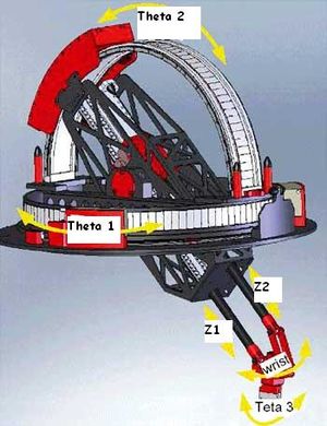
| + | === Dynamic Model 1 === | ||
| + | |||
| + | [[File:GSR-SETUP.JPG|thumb|Galileo robot]] | ||
| + | |||
| + | | ||
| + | |||
| + | | ||
| + | {| border="1" width="80%" | ||
| + | |- | ||
| + | ! width="100" | Number | ||
| + | ! width="250" | Parameter | ||
| + | ! Comments | ||
| + | |- | ||
| + | | 1 | ||
| + | | m<sub>P</sub> | ||
| + | | Payload mass [kg] | ||
| + | |- | ||
| + | | 2 | ||
| + | | m<sub>B</sub> | ||
| + | | Balance mass [kg] | ||
| + | |- | ||
| + | | 3 | ||
| + | | T<sub>P</sub> | ||
| + | | Payload mass center distance from the flange [mm] | ||
| + | |- | ||
| + | | 4 | ||
| + | | T<sub>B</sub> | ||
| + | | Balance mass center distance from the (0,0) [mm] | ||
| + | |- | ||
| + | | 5 | ||
| + | | I<sub>R</sub> | ||
| + | | Inertia of the payload around roll [kg*m<sup>2</sup> | ||
| + | |} | ||
| − | [[Category: | + | [[Category:Pages with broken file links]] [[Category:Motion Dynamics]] |
Latest revision as of 12:51, 2 February 2025
This page gives an overview over all implemented dynamic models.
General considerations
- Friction is handled on axis basis. The parameters for friction, COULOMBFRICTION and VISCOUSFRICTION, are set for each axis separately.
- Torque (Force) is always expressed in [Nm] ([N])
- The dynamic model number is the value of <element>.DYNAMICMODEL
- The property numbers are the indexes of <element>.DYNAMICPARAMETER[<number>]
Contents
Rotational Axes
Dynamic Model 1 - simple rotary axis
| Number | Parameter | Comments |
|---|---|---|
| 1 | Total moment of inertia around the rotation axis of the moved part |
- Model equation
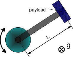
Dynamic Model 2 - horizontal crank-arm axis
| Number | Parameter | Comments |
|---|---|---|
| 1 | Total moment of inertia around the rotation axis of the moved part | |
| 2 | Square of length of crank arm (axis to payload) |
- Model equation
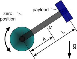
Dynamic Model 3 - vertical crank-arm axis
| Number | Parameter | Comments |
|---|---|---|
| 1 | Total moment of inertia around the rotation axis of the moved part | |
| 2 | Square of length of crank arm (axis to payload) | |
| 3 | Mass (without payload) * Gravity * Distance to center of mass | |
| 4 | Gravity * Distance to Payload |
- Model equation
Linear Axes
Dynamic Model 1 - horizontal axis
| Number | Parameter | Comments |
|---|---|---|
| 1 | Total mass of the moved part. |
- Model equation
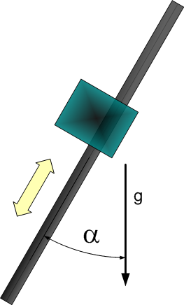
Dynamic Model 2 - vertical or tilted axis
| Number | Parameter | Comments |
|---|---|---|
| 1 | Total mass of the moved part. | |
| 2 | Constant force due to gravity. | |
| 3 | Gravity coefficient used to consider payload mass. (g = 9.80665) |
- Model equation
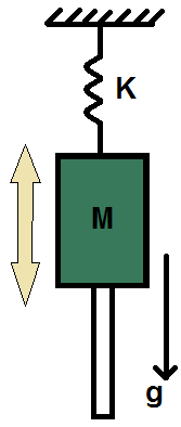
Dynamic Model 3 - vertical axis with a spring
| Number | Parameter | Comments |
|---|---|---|
| 1 | Total mass of the moved part. [kg] | |
| 2 | The stiffness constant of the spring. [kg/s^2] | |
| 3 | The stiffness constant times the relaxation position of the spring. [kg*m/s^2] |
- Model equation
Traverse Arm Robots
Dynamic Model 1
| Number | Parameter | Comments |
|---|---|---|
| 1 | ||
| 2 | ||
| 3 | ||
| 4 | ||
| 5 | ||
| 6 | ||
| 7 |
Scara Robots
The dynamic equations of the robot are expressed at the outputs of the gearboxes attached to the actuation motors. Therefore, the torques, joint positions, velocities, and accelerations are those of the gearbox output shafts.
In the following models, the variable for is the mass of link . Link is a ball screw. The variable is the lead of the ball screw, i.e. the linear distance traveled for each complete turn of the screw. The internal units of are [mm/deg], while its user units are [m/rad].
The variables and are the lengths of links and . The variables and are respectively the distances of the exes of joints and to the centers of mass of links and .
The variable for is the moment of inertia of link , relative to a reference frame attached to the link's center of mass, and about the link's axis of rotation.
Additionally, for is the moment of inertia of rotor , reflected to the gearbox output shaft as follows. Let be the moment of inertia of rotor relative to a reference frame attached to the rotor's center of mass, about the rotor's axis of rotation. Let be the gear ratio of the gearbox or pulley system, then .
The variables and are respectively the payload mass and payload moment of inertia relative to its center of mass. If no object or gripper is attached to the robot, the value of these variables is zero.
Dynamic Model 1
For non-coupled SCARA robots (axis 3 and 4 are not coupled) and for concentric payloads (concentric with axis 4).
| Number | Parameter | Comments |
|---|---|---|
| 1 | kg*m2 | |
| 2 | kg*m2 | |
| 3 | kg*m2 | |
| 4 | kg*m2 | |
| 5 | kg | |
| 6 | kg*m/sec2 | |
| 7 | kg*m2 | |
| 8 | kg*m2 |
Dynamic Model 2
For coupled SCARA robots (axis 3 and 4 are coupled) and for concentric payloads (concentric with axis 4).
| Number | Parameter | Comments |
|---|---|---|
| 9 | kg*m2 | |
| 10 | kg*m2 | |
| 11 | kg*m2 | |
| 12 | kg | |
| 13 | kg*m2 | |
| 14 | kg*m2 | |
| 15 | kg | |
| 16 | kg*m2 |
The payload parameters for Dynamic Model 1 and Dynamic Model 2 are:
| Number | Parameter | Comments |
|---|---|---|
| 1 | payloadMass | , the mass of the payload |
| 2 | payloadInertia | , the payload's moment of inertia relative to its center of mass |
Dynamic Model 3
For coupled SCARA robots (axis 3 and 4 are coupled) and for non-concentric payloads (the payload center of mass is not located along axis 4, and is located on the x-axis of the tool flange, which is defined by the zero position of axis 4).
The dynamic parameters are the same as model 2, except for parameter No. 13.
The payload parameters are:
| Number | Parameter | Comments |
|---|---|---|
| 1 | payloadMass | , the mass of the payload |
| 2 | payloadInertia | , the payload's moment of inertia relative to its center of mass |
| 3 | payloadLx | the distance [m] to the center of mass from the 4th axis in the x direction |
| 13 | [kg*m2], includes the additional term in accordance with the parallel axis theorem |
When using identification with this model, all of the payload parameters can be found.
Dynamic Model 4
Same as Dynamic Model 3.
This model is used in identification process in order to identify the payloadMass parameter only, by moving only joint number 3.
Dynamic Model 5
Same as Dynamic Model 3.
This model is used in identification process in order to identify the payloadInertia and payloadLx parameters, by moving only joint number 4 and very small movements in joints 1 and 2.
Delta Robots
Dynamic Model 1
Dynamic model of 3 DOF DELTA robot.
| Number | Parameter | Comments |
|---|---|---|
| 1 | kg*m2 | |
| 2 | kg*m2/sec2 | |
| 3 | kg | |
| 4 | kg*m2 | |
| 5 | kg | |
| 6 | kg | |
| 7 | kg*m2 | |
| 8 | kg*m2 | |
| 9 | m | |
| 10 | m | |
| 11 | ||
| 12 | ||
| 13 | ||
| 14 |
Dynamic Model 2
Dynamic model of 4 DOF DELTA robot, with rotary 4th axis. The basic parameters are identical to those of DynamicModel = 1, with the calculation of the additional parameters of axis 4. The assumption is dynamic decoupling of the first three axes from the 4th axis.
Puma Robots
Dynamic Model 1
Description:
-
- - Gravity constant
- - Mass of the ith link
- - length of the common normal between the ith and ith+1 joints
- - offset along z axis between the ith and ith+1 joints
- - The distance from the ith joint to the center of mass of the ith link
| Number | Parameter | Comments |
|---|---|---|
| 1 | |
kg*m^2 |
| 2 | kg*m^2 | |
| 3 | kg*m^2 | |
| 4 | kg*m^2 | |
| 5 | kg*m^2 | |
| 6 | Failed to parse (MathML with SVG or PNG fallback (recommended for modern browsers and accessibility tools): Invalid response ("Math extension cannot connect to Restbase.") from server "https://en.wikipedia.org/api/rest_v1/":): {\displaystyle I_{6} = I_{3,zz}+m_{3}*l_{3,y}^2+m_{4}*a_{3}^2+m_{4}*(d_{4}+l_{4,z})^2+I_{4,yy}+m_{5}*a_{3}^2+m_{5}*d_{4}^2+I_{5,zz}+m_{6}*a_{3}^2+m_{6}*d_{4}^2+m_{6}*l_{6,z}^2+I_{6,xx}} | kg*m^2 |
| 7 | Failed to parse (MathML with SVG or PNG fallback (recommended for modern browsers and accessibility tools): Invalid response ("Math extension cannot connect to Restbase.") from server "https://en.wikipedia.org/api/rest_v1/":): {\displaystyle I_{7} = m_{3}*l_{3,y}^2+I_{3,xx}-I_{3,yy}+m_{4}*l_{4,z}^2+2*m_{4}*d_{4}*l_{4,z}+(m_{4}+m_{5}+m_{6})*(d_{4}^2-a_{3}^2)+I_{4,yy}-I_{4,yy}+I_{5,zz}-I_{5,yy}+m_{6}*l_{6,z}^2-I_{6,zz}+I_{6,xx}} | kg*m^2 |
| 8 | Failed to parse (MathML with SVG or PNG fallback (recommended for modern browsers and accessibility tools): Invalid response ("Math extension cannot connect to Restbase.") from server "https://en.wikipedia.org/api/rest_v1/":): {\displaystyle I_{8} = -m_{4}*(d_{2}+d_{3})*(d_{4}+l_{4,z})-(m_{3}+m_{6})*(d_{2}+d_{3})*d_{4}+m_{3}*l_{3,y}*l_{3,z}+m_{3}*(d_{2}+d_{3})*l_{3,y}} | kg*m^2 |
| 9 | Failed to parse (MathML with SVG or PNG fallback (recommended for modern browsers and accessibility tools): Invalid response ("Math extension cannot connect to Restbase.") from server "https://en.wikipedia.org/api/rest_v1/":): {\displaystyle I_{9} = m_{2}*l_{2,y}*(d_{2}+l_{2,z})} | kg*m^2 |
| 10 | Failed to parse (MathML with SVG or PNG fallback (recommended for modern browsers and accessibility tools): Invalid response ("Math extension cannot connect to Restbase.") from server "https://en.wikipedia.org/api/rest_v1/":): {\displaystyle I_{10} = 2*m_{4}*a_{5}*l_{4,z}+2*(m_{4}+m_{5}+m_{6})*a_{3}*d_{4}} | kg*m^2 |
| 11 | Failed to parse (MathML with SVG or PNG fallback (recommended for modern browsers and accessibility tools): Invalid response ("Math extension cannot connect to Restbase.") from server "https://en.wikipedia.org/api/rest_v1/":): {\displaystyle I_{11} = -2*m_{2}*l_{2,x}*l_{2,y}} | kg*m^2 |
| 12 | Failed to parse (MathML with SVG or PNG fallback (recommended for modern browsers and accessibility tools): Invalid response ("Math extension cannot connect to Restbase.") from server "https://en.wikipedia.org/api/rest_v1/":): {\displaystyle I_{12} = (m_{4}+m_{5}+m_{6})*a_{2}*a_{3}} | kg*m^2 |
| 13 | Failed to parse (MathML with SVG or PNG fallback (recommended for modern browsers and accessibility tools): Invalid response ("Math extension cannot connect to Restbase.") from server "https://en.wikipedia.org/api/rest_v1/":): {\displaystyle I_{13} = (m_{4}+m_{5}+m_{6})*a_{3}*(d_{2}+d_{3})} | kg*m^2 |
| 14 | Failed to parse (MathML with SVG or PNG fallback (recommended for modern browsers and accessibility tools): Invalid response ("Math extension cannot connect to Restbase.") from server "https://en.wikipedia.org/api/rest_v1/":): {\displaystyle I_{14} = I_{4,zz}+I_{5,yy}+I_{6,zz}} | kg*m^2 |
| 15 | Failed to parse (MathML with SVG or PNG fallback (recommended for modern browsers and accessibility tools): Invalid response ("Math extension cannot connect to Restbase.") from server "https://en.wikipedia.org/api/rest_v1/":): {\displaystyle I_{15} = m_{6}*d_{4}*l_{6,z}} | kg*m^2 |
| 16 | Failed to parse (MathML with SVG or PNG fallback (recommended for modern browsers and accessibility tools): Invalid response ("Math extension cannot connect to Restbase.") from server "https://en.wikipedia.org/api/rest_v1/":): {\displaystyle I_{16} = m_{6}*a_{2}*l_{6,z}} | kg*m^2 |
| 17 | Failed to parse (MathML with SVG or PNG fallback (recommended for modern browsers and accessibility tools): Invalid response ("Math extension cannot connect to Restbase.") from server "https://en.wikipedia.org/api/rest_v1/":): {\displaystyle I_{17} = I_{5,zz}+I_{6,xx}+m_{6}*l_{6,z}^2} | kg*m^2 |
| 18 | Failed to parse (MathML with SVG or PNG fallback (recommended for modern browsers and accessibility tools): Invalid response ("Math extension cannot connect to Restbase.") from server "https://en.wikipedia.org/api/rest_v1/":): {\displaystyle I_{18} = m_{6}*(d_{2}+d_{3})*l_{6,z}} | kg*m^2 |
| 19 | Failed to parse (MathML with SVG or PNG fallback (recommended for modern browsers and accessibility tools): Invalid response ("Math extension cannot connect to Restbase.") from server "https://en.wikipedia.org/api/rest_v1/":): {\displaystyle I_{19} = I_{4,yy}-I_{4,xx}+I_{5,zz}-i_{5,yy}+m_{6}*l_{6,z}^2+I_{6,xx}-I_{6,zz}} | kg*m^2 |
| 20 | Failed to parse (MathML with SVG or PNG fallback (recommended for modern browsers and accessibility tools): Invalid response ("Math extension cannot connect to Restbase.") from server "https://en.wikipedia.org/api/rest_v1/":): {\displaystyle I_{20} = I_{5,yy}-I_{5,xx}-m_{6}*l_{6,z}^2+I_{6,zz}-I_{6,xx}} | kg*m^2 |
| 21 | Failed to parse (MathML with SVG or PNG fallback (recommended for modern browsers and accessibility tools): Invalid response ("Math extension cannot connect to Restbase.") from server "https://en.wikipedia.org/api/rest_v1/":): {\displaystyle I_{21} = I_{4,xx}-I_{4,yy}+I_{5,xx}-I_{5,zz}} | kg*m^2 |
| 22 | Failed to parse (MathML with SVG or PNG fallback (recommended for modern browsers and accessibility tools): Invalid response ("Math extension cannot connect to Restbase.") from server "https://en.wikipedia.org/api/rest_v1/":): {\displaystyle I_{22} = m_{6}*a_{3}*l_{6,z}} | kg*m^2 |
| 23 | Failed to parse (MathML with SVG or PNG fallback (recommended for modern browsers and accessibility tools): Invalid response ("Math extension cannot connect to Restbase.") from server "https://en.wikipedia.org/api/rest_v1/":): {\displaystyle I_{23} = I_{6,zz}} | kg*m^2 |
Dynamic Model 2 - Gravity
This dynamic model is for cases where the robot moves very slowly.
In such cases, the accelerations and velocities of the joints of the robot have little effect on the joints torques. The joints torques are mainly affected by gravity and friction.
This model includes only the gravity and friction part of the PUMA robot dynamic model.
| Number | Parameter | Comments |
|---|---|---|
| 1 | Failed to parse (MathML with SVG or PNG fallback (recommended for modern browsers and accessibility tools): Invalid response ("Math extension cannot connect to Restbase.") from server "https://en.wikipedia.org/api/rest_v1/":): {\displaystyle g(m_{2}l_{2}+a_{2}(m_{3}+m_{4}+m_{5}+m_{6}))} | kg*m^2/s^2 |
| 2 | Failed to parse (MathML with SVG or PNG fallback (recommended for modern browsers and accessibility tools): Invalid response ("Math extension cannot connect to Restbase.") from server "https://en.wikipedia.org/api/rest_v1/":): {\displaystyle g(m_{3}l_{3,y}+a_{3}(m_{4}+m_{5}+m_{6}))} | kg*m^2/s^2 |
| 3 | Failed to parse (MathML with SVG or PNG fallback (recommended for modern browsers and accessibility tools): Invalid response ("Math extension cannot connect to Restbase.") from server "https://en.wikipedia.org/api/rest_v1/":): {\displaystyle g(m_{3}l_{3,y}+m_{4}(l_{4}+d_{4}(m_{5}+m_{6}))} | kg*m^2/s^2 |
| 4 | Failed to parse (MathML with SVG or PNG fallback (recommended for modern browsers and accessibility tools): Invalid response ("Math extension cannot connect to Restbase.") from server "https://en.wikipedia.org/api/rest_v1/":): {\displaystyle gl_{56}(m_{5}+m_{6})} | kg*m^2/s^2 |
Galileo Spherical Robots (GSR)
Dynamic Model 1
| Number | Parameter | Comments |
|---|---|---|
| 1 | mP | Payload mass [kg] |
| 2 | mB | Balance mass [kg] |
| 3 | TP | Payload mass center distance from the flange [mm] |
| 4 | TB | Balance mass center distance from the (0,0) [mm] |
| 5 | IR | Inertia of the payload around roll [kg*m2 |


