Single Axis Setup in EtherCAT/CANopen Network

| Language: | English |
|---|
Contents
- 1 Introduction
- 2 Procedures
- 2.1 Step 1: Install and activate ControlStudio
- 2.2 Step 2: Install device parameter (library) file on PC
- 2.3 Step 3: Create a folder for the ControlStudio machine application
- 2.4 Step 4: Make the cable connections
- 2.5 Step 5: Establish communication between PC and softMC
- 2.6 Step 6: Create a Configurator project.
- 2.7 Step 7: Define axis A1 configuration settings
- 2.8 Step 8: Define axis A2 configuration settings
- 2.9 Step 9: Compile project files and send configuration to the softMC
- 2.10 Step 10: Verify the configuration by moving the axes
- 2.11 Step 11: Record a motion
- 2.12 step 12: Work with softMC controller via Terminal
- 2.13 step 13: Write and run a program
- 3 Appendices
Introduction
Note: Only essential background information is included in this training manual. For downloads and more information about the softMC hardware and software systems, use the resources available on the Servotronix website.
ControlStudio is a PC-based graphical user interface for developing and testing motion applications controlled and/or coordinated by the softMC. ControlStudio contains a programming editor, data recorder, debugger and monitoring tools. Once the application programs are completed, the PC can be removed and the softMC controller can operate standalone or within a network.
softMC Configurator is a wizard that is bundled with ControlStudio. The Configurator is used to define the axes and IOs to be controlled in the motion application; it then generates a set of programs and files for initializing the softMC.
MC-Basic (Motion Control BASIC) is the proprietary programming language developed by Servotronix for use with the softMC. It is based on standard BASIC programming language, with extensive enhancements for multi-tasking and motion control functionalities.
Procedures
Step 1: Install and activate ControlStudio
Windows
- If any previous versions of softMC are installed on the PC, uninstall them.
For instructions, refer to Appendix A of this document and/or contact Technical Support. - Run CSSetup.exe to install ControlStudio.
Accept the default settings during the installation.
Four programs are installed. - If not already opened, activate ControlStudio (from the Start menu or desktop icon).
Step 2: Install device parameter (library) file on PC
ControlStudio Offline
- From the ControlStudio menu bar, activate the softMC Configurator.
Select: Tools > softMC Configurator
Note: Always activate Configurator from ControlStudio (and not from the desktop icon). - When operating offline, the Configurator looks like this.
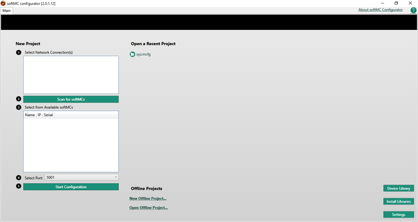
At the bottom of the Configurator screen, click Install Libraries.
Note: Libraries is a file that contains the parameters of all devices (such as CDHD, stepIM, IOs) that can be controlled by the softMC.
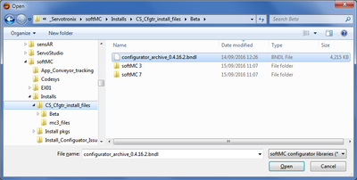
An updated Libraries file must be installed on the PC whenever new controller firmware is installed. - Browse to the folder containing the file configurator_archive_0.4.x.x.bndl
This is the Libraries file.
Click Open.
Wait for the confirmation message: Libraries successfully imported.
Click OK. - Close Configurator.
Note: Do not minimize. You must close Configurator.


Step 3: Create a folder for the ControlStudio machine application
ControlStudio offline
At the bottom of the ControlStudio screen, click to open the File Manager.
- The File Manager has three panes.
- In the left pane, select the location where you want to create a folder for your application files.
- In the middle pane, right click, and select New Folder.
- Give a name to the new folder: EX01

- Note: The motion application (Solution) developed in ControlStudio will contain Project and Subproject folder/s that hold task (program) files, library files, and data files. The PC file system does not reflect the softMC controller file system.
Step 4: Make the cable connections
- Connect the system cables, if not already connected.
Refer to diagrams below.
For more instructions, refer to the softMC Installation Guide.
Note: If using ServoStudio for motor setup and/or drive tuning, a Kvaser adapter will be needed to enable serial communication with the PC. Refer to the stepIM Technical Training Manual or contact Technical Support.
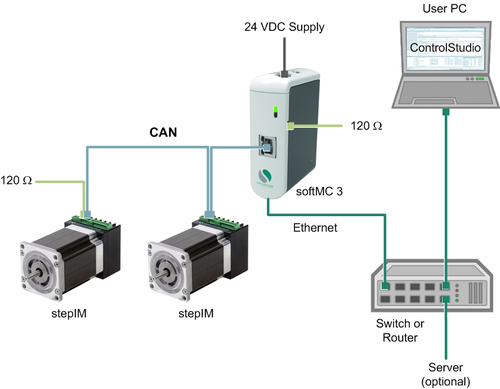
softMC 3 with stepIM - Training Setup - CANopen devices and network
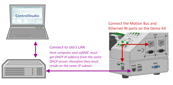
softMC 7 with CDHD – Training Setup - EtherCAT devices and network
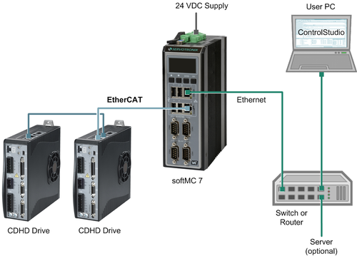
- Turn on the softMC training system.


Step 5: Establish communication between PC and softMC
ControlStudio online
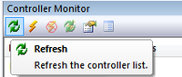
- At the right side of the ControlStudio screen, hover over Controller Monitor.
The Controller Monitor pane opens.
Click the Refresh button.
Wait a few moments until the softMC in your setup is recognized and displayed in the list. (e.g., “DEMO”)
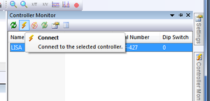
- Select the detected softMC, and click the Connect button.
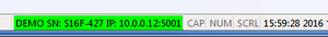
- The communication status at the bottom of the screen turns green, indicating that the softMC and ControlStudio are communicating.
- In the middle of the ControlStudio screen, you will see the Terminal pane.
Note: The Terminal is a command line interface to the softMC. It allows you to send commands and queries to the softMC, and receive responses in return.
To confirm communication has been established, place the cursor in the Terminal pane.
Query the firmware version: ?ver
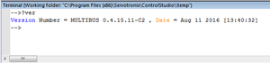
Make sure the response to the version query is 0.4.16.2 or later.
If necessary, update the softMC firmware. For instructions, refer to Appendix B of this document and/or contact Technical Support.
- If the training system has not been used previously, skip to Procedure 6.
If the training system has been used previously, program config.prg must first be cleared of all program lines. Contact Technical Support for instructions.


Step 6: Create a Configurator project.
Configurator online
- Open Configurator.
Access through: Tools > softMC Configurator
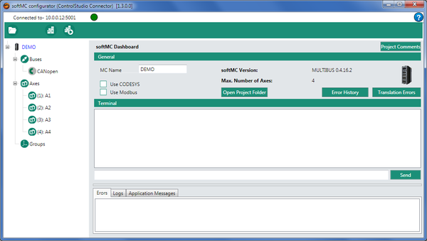
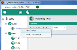
If using CANopen network, the Configurator online screen will look like this:
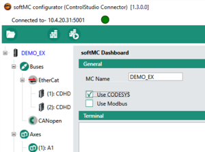
If using EtherCAT network, the Configurator online screen will look like this:
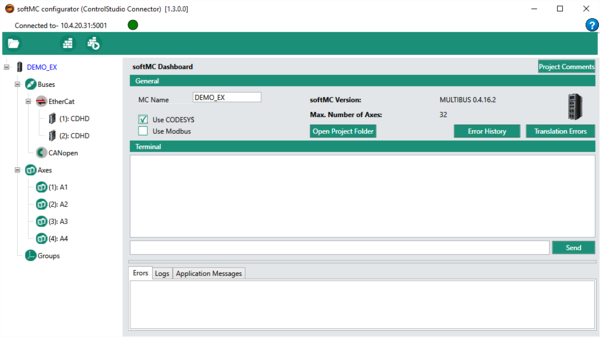
If using EtherCAT network, select the option: Use CODESYS - Optional: In the MC Name field, enter a name for the softMC; e.g., DEMO_EX
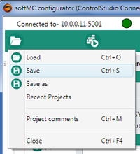
- Create a Configurator project (called EX01) by saving a file to the softMC folder created previously (Step 3).
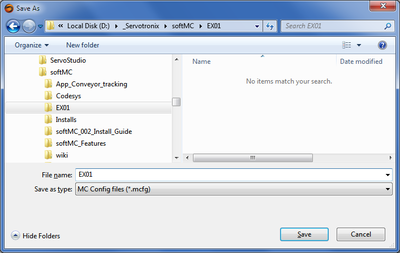
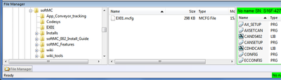
- In ControlStudio (online), go to the File Manager pane at the bottom of the screen.
Select folder EX01 in the left pane, and look at the middle pane.
If files do not appear, right-click in the middle pane > Refresh List
You will see a file named EX01.mcfg = Configurator project file


Step 7: Define axis A1 configuration settings
Configurator online
- Define Axis A1.
If using EtherCAT devices/drives, they will automatically be detected and displayed. Skip to Step 7.3.
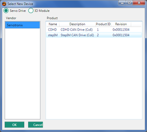
If using CANopen devices/drives, right-click on CANopen in the navigation pane.
Select New Device.
- If using CANopen devices/drives, select Servotronix > stepIM or CDHD.
Click OK.
- Depending on the selected device, stepIM or CDHD now appears in the Buses section of the navigation pane.
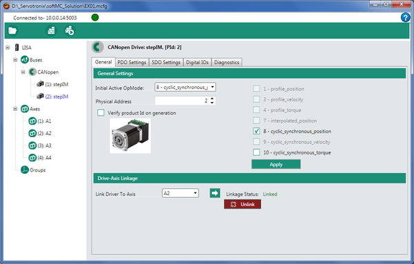
Select a drive (stepIM or CDHD). Selected device is displayed in blue text.
Enter settings as shown below.
Initial Active OpMode = 8-Cyclic synchronous position
Physical Address = 1
Click Apply.
Link Drive to Axis = A1.
Click the Link arrow.
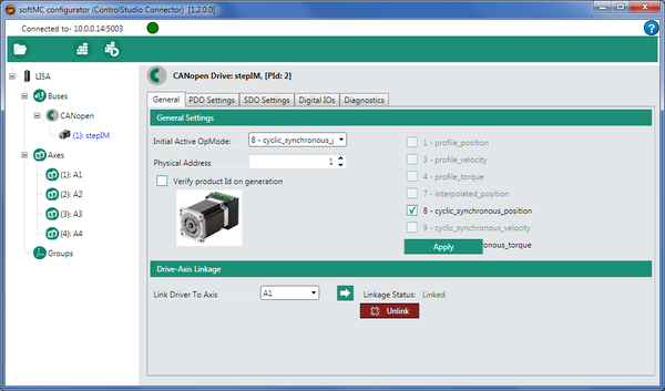
Note: For proper operation, Initial Active OpMode must be set to 8-Cyclic synchronous position - Configurator displays the Axis:A1 screen.
The screen has four tabs: General, Properties, Movement and Graph.
In the General tab, enter settings as shown below.
Axis Type = Rotary Gear
Length Units = Degrees (default)
Gear Ratio = 1.0
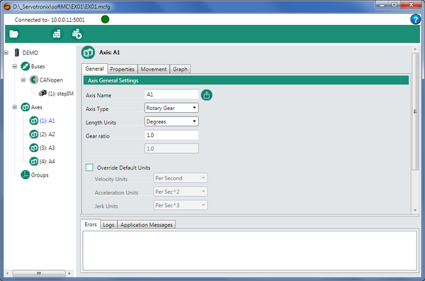
Note: A gear ratio value is usually in the range 10—160.
When using a Servotronix Demo Kit, Gear Ratio value = 1. - Guidelines
Most robotic applications are programmed in units of degree/second, that is, 360 deg = 1 revolution. Therefore:
6 deg/sec = 1 rpm
120 deg/sec = 20 rpm
360 deg/sec = 60 rpm
The instructions in this document use the following calculations and values, which are typical for a brushless DC motor:
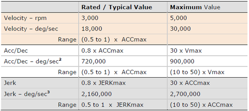
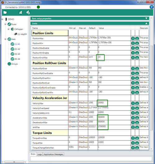
Use the same value for both acceleration and deceleration. However, if the Load to Motor Inertia Ratio ratio is less than 10 (optimal LMJR value), a higher acceleration can be used. - In the Properties tab, click on the Limits bar to access Limit parameters.
Change the values of the following parameters:
Position Error Max = 10
Velocity Max = 30000
Acceleration Max = 900000
Deceleration Max = 900000
Jerk Max = 2700000
After typing in a value, be sure to press Enter.
- Save Configurator project (EX01.mcfg)


Step 8: Define axis A2 configuration settings
Configurator online
- Define the parameters for Axis A2 by repeating the steps in Step 7.
- Save Configurator project (EX01.mcfg)

Step 9: Compile project files and send configuration to the softMC
Configurator online
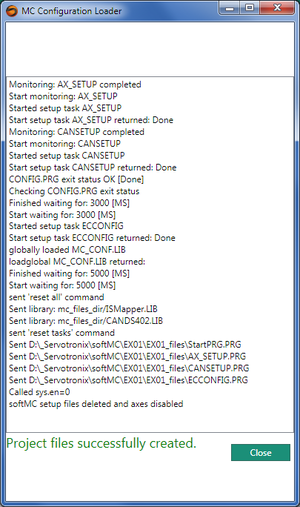
- In the Configurator menu bar, click the Build & Run button.

- The Configurator generates files on the PC and sends them to the softMC.
When complete, click Close.
- Save Configurator project (EX01)
- ControlStudio online
Note: Configurator generates a ControlStudio project file called EX01.APJ file.
Configurator generates a folder called EXO1_Files
In ControlStudio, go to the File Manager pane at the bottom of the screen.
Select folder EX01 in the left pane, and look at the middle pane.
If files do not appear, right-click in the middle pane > Refresh List
Note: Files in the right pane reside in the softMC. Do not click on these files, or attempt to manipulate them.
If using an EtherCAT network and devices and Use CODESYS option was selected, the EX01_Files folder will contain an additional file called softmc.devdesc.xml

Step 10: Verify the configuration by moving the axes
Configurator online
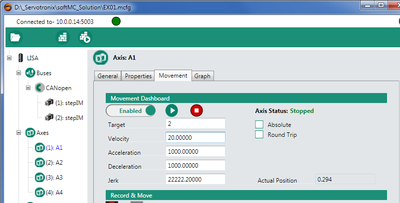
- Select Axis A1, and open the Movement tab.
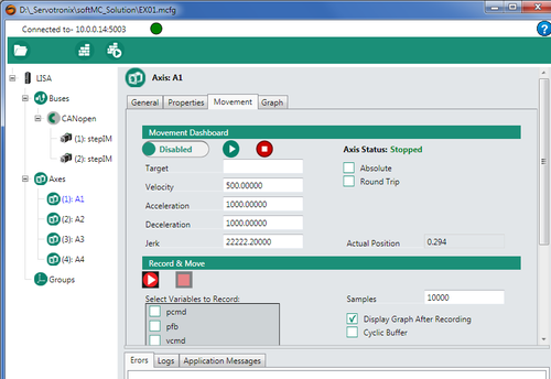
- Refer to the units of motion table in Step 7.
Change the values of the following parameters:
Set Target = 360 (1 revolution)
Set Velocity = 120
Set Acceleration and Deceleration = 720000
Set Jerk = 2160000
Make sure Absolute option is not selected.
Move the switch to Enabled.
Click the Run button.
Watch motor 1 load disk – it will rotate once.
:
Enable the Absolute option.
Set Target to 0.
Click Run.
When motor stops, note the Actual Position. It will show 0.000
- Select Axis A2, and in the Movement tab, and enter the same settings as above.
Click the Run button.
Watch motor 2 load disk – it will rotate once.
Enable the Round Trip option.
Click Run.
Watch motor 2 load disk – it will rotate once in each direction. - Disable both axes.
- Save the Configurator project.


Step 11: Record a motion
Configurator online
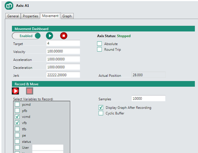
- Select Axis A1, and open the Movement tab.
- Change the values of the following parameters:
Target = 360 (1 revolution)
Velocity = 360 (60 rpm)
Acc/Dec = 720000 deg/sec
Jerk = 2160000 deg/sec
Clear the Absolute option.
Clear the Round Trip option.
Enable the option Display Graph After Recording
Select Variables: VCMD and VFB.
Clear all other variables.
Make sure drive is Enabled.
Click Record &Move button
- In a few moments, the recorded plot appears in the Graph tab.
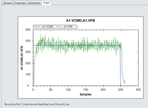
Note: The recorded plot is saved in a A1.rec (A2.rec) file in a temp folder. The last recording always overwrites the previous recording.
The Configurator recording function is only intended to provide initial confirmation of the axis configuration. For complete testing and adjustment, use the Recording function within ControlStudio. - In the Movement tab, disable the axes
- Save the Configurator project.
Exit Configurator


step 12: Work with softMC controller via Terminal
ControlStudio online
- If softMC has been power cycled, this step is required. Otherwise, skip to Step 12.3.
In the Terminal pane, enter the command reset all
Note: The command reset all does the following:- Removes all system variables and tasks from controller RAM.
- Removes all files from controller RAM .
- Runs the CONFIG.PRG task
- If softMC has been power cycled, this step is required. Otherwise, skip to Step 12.3.
In the Terminal pane, enter the command load startprg.prg
Note: The command load startprg.prg loads all configuration data from controller Flash (non-volatile) memory to RAM. Data remains in Flash memory.
Look at the messages in the Message Log pane.
The system is now ready to receive commands. - In the Terminal pane, enable the axes.
- Enable axis 1: a1.en=1
- Enable axis 2: a2.en=1
Gently grasp the motor load disk and try to move them. Strong resistance indicates the motor is enabled.
- Enable axis 1: a1.en=1
- Note: The Move executes a point-to-point move from the current position to the target position of a single axis or a group of axes.
Note: Use F3 as a shorcut to repeat last command entered
In the Terminal pane, execute Move commands, and observe the response of the motors.
• Move A1 and A2 to absolute position PFB 0:
→move a1 0 abs=1
→move a2 0 abs=1
• Move A1 and A2 to absolute position PFB 3600 (10 revolutions from 0):
→move a1 3600 abs=1
→move a2 3600 abs=1
• Move A1 one revolution counterclockwise:
→move a1 -360 abs=0
• Move A2 two revolution clockwise:
→move a2 720
• Move A1 and A2 to absolute position PFB 7200 at different speeds:
→move a1 7200 abs=1 vcruise=720
→move a2 7200 abs=1 vcruise=240 - Note: Jog moves the axis at a constant velocity.
Use the Stop command to stop a Jog motion.
In the Terminal pane, execute Jog commands, and observe the response of the motors:
→jog a1 720
→jog a2 240
Allow both motors to run simultaneously.
Then stop the motion:
→stop a1
→stop a2
Disable the axes.
step 13: Write and run a program
ControlStudio online
- To begin writing a program for your motion application:
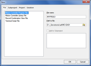
In ControlStudio, select: File → New → File
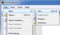
- In the New' dialog box, do the following:
Select Motion Controller Program File.
Enter a name for your program (e.g., MYPROG1).
Note: A program name cannot exceed 8 characters.
Browse to and select the path/folder containing your application files (e.g., EX01)
- The Program Editor pane opens in ControlStudio.
The pane has a tab for the new program, containing a blank program template.
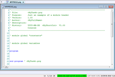
- Insert the cursor in the line below program.
Enter the following program lines:
program
attach a1
attach a2
a1.En=1
a2.En =1
move a1 720 abs=1 vcruise= 360
move a2 1440 abs=1 vcruise= 360
delay a1 1000
delay a2 1000
move a1 0 abs=1
cruise=360
move a2 0 abs=1 vcruise= 360
delay a1 10
delay a2 10
a1.En=0
a2.En=0
detach a1
detach a2
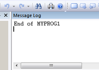
Print "End of MYPROG1"
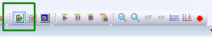
end program - Save the program: File > Save
Alternately, click the Save button on the toolbar.
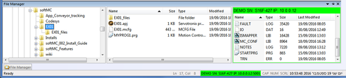
Check the File Manager pane at the bottom of the screen. Refresh if necessary.
You now see the program in the application folder.
- Send program MYPROG1 to the controller.
Click the Save and Load button in the ControlStudio menu bar.
- Run the program.
Click the Continue Task button in the ControlStudio menu bar.
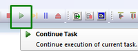
Observe the motion of the two motors.
When motion stops, note the message in the Message Log pane:
- Run the program one line at a time.
Click the Step by Step button in the ControlStudio menu bar.
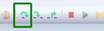
Continue clicking and observing the motion of the two motors.


Appendices
Appendix A: Uninstall previous ControlStudio installation
Windows
- Uninstall all previously installed softMC programs.
You can identify and uninstall the programs to be removed according to the publisher name: Servotronix.
Note: Do not uninstall ServoStudio by Servotronix.
Appendix B: Update the softMC firmware
ControlStudio online
- To update the firmware:
Tools > Firmware Update - At the prompt, click Update.
- Browse to the folder containing the firmware zip file.
Select the file and click Open. - Follow the prompts.
During the firmware update, the controller power cycles automatically.
The Communication status indication turns yellow.
Wait for the yellow LED on the front of the Demo Kit to turn off.
To reestablish communication, use the Reset Communication button in the Controller Monitor pane (or Ctrl+D). - When finished, check the version again.
If it does not appear to be updated, turn the controller off and then on again.
Make sure Communication status indicates Connected.