Project Example: Label Machine (Function Block Diagram)
| Language: | English • 中文(简体) |
|---|
The task is to place a label at a particular position on a product.
The application has two drives: one to feed the product via a conveyor belt, the other to feed labels and to place them on the moving products.
The labeling process is triggered by a position-detection sensor.
From the detection of the product to the start of the label movement, there is a delay that depends on the velocity of the conveyor, the position of the sensor and the position of the label on the product.
Both axes move with the same velocity set point.
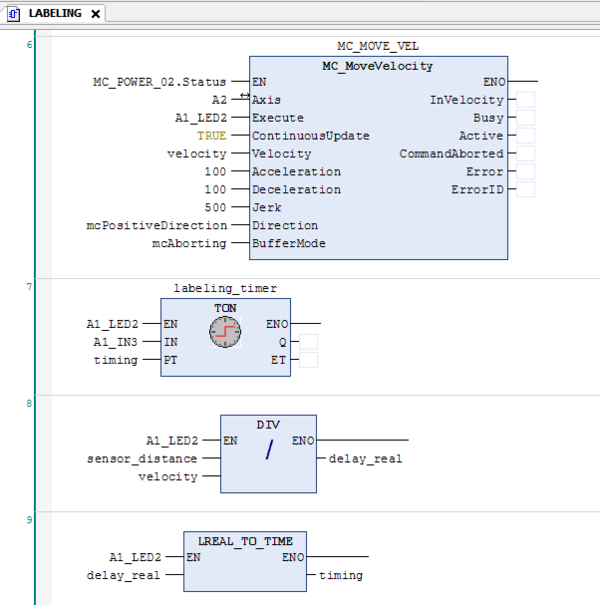
The delay for TON FB is calculated from the sensor distance and the velocity. After a labeling step, the Label Drive stops again and waits for the next trigger, while the conveyor continuously moves.
The main program initializes a startup process in the softMC.
After the startup process is done, the program sets 'Done' variable and a global variable.
After 'Done' variable is set, program 'Labeling' is called.
The application uses two drives and their outputs.
After installation of device description file (created by the Configurator) to Device Repository, the drive's address will be declared in the Axis Pool:
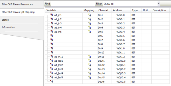
In the EtherCAT Slaves section, we can find the I/O mapping for each device.
In the picture below Input1, Input2, Input3, Input4, Input5, Input11, Output1, Output2, Output3, Output4 and Output5 are declared as new variables (can also be mapped as existing variables):
The main program uses 'softMC_Startup' FB ('mc_st' Instance) to initialize a startup process in the softMC.
A rising edge detection will set the 'Done' variable (and also a global variable) and then call program 'Labeling':
Labeling POU - Declaration Section
The declaration section in the Labeling program contains the following instances (as shown in the next picture):
1. MC_POWER_01 - an instance of MC_Power FB.
This Function Block enables/disables an axis.
If the axis is associated with a real drive, a state machine is invoked to enable/disable the drive via PDO.
If the axis is simulated, a MC-Basic subroutine is invoked to enable/disable the axis.
2. MC_MoveVelocity_01 - an instance of MC_MoveVelocity FB.
This Function Block commands a never ending controlled motion at a specified velocity.
3. MC_halt_01 - an instance of MC_halt FB.
This Function Block commands a controlled motion stop. The axis is moved to the state ‘DiscreteMotion’, until the velocity is zero. With the ‘Done’ output set, the state is transferred to ‘Standstill’.
4. MC_MoveRelative_01 - an instance of MC_MoveRelative FB.
This Function Block commands a controlled motion of a specified distance relative to the set position at the time of the execution.
5. labeling_timer - an instance of TON FB (On-Delay timer).
Labeling POU - Implementation Section
Output5 is turned on when Labeling POU is called.
Input1 (of both drives) will turn on Output1 (of both drives).
Input2 (of both drives) will turn on Output2 when Output1 of drive 2 is on (of both drives).
If Output1 is triggered, the MC_Power FB is enabled (for both drives).
If drive 2 is enabled and Output2 of drive 1 is on, then Axis 2 will rotate in a constant velocity.
Input3 of drive 1 is the product sensor detection input.
If Output2 of drive 1 is on, then a timer will start counting when Input3 of drive 1 is turned on for 'timing' (PT) seconds.
In addition, a calculation of the time delay is inserted into 'delay_real' and then converted from 'real' units to time units.
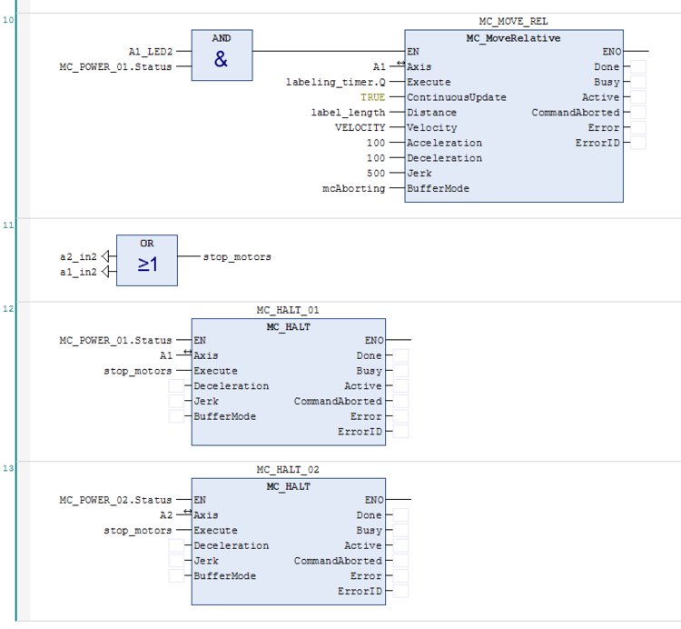
When the timer has elapsed (Output2 is still on and drive 1 is still enabled), axis 1 will move in the configured 'label_length' distance.

When a falling edge is detected in Input2 of drive 1 or drive 2, then a boolean variable 'stop_motors' is triggered.
If drives are enabled, then when 'stop_motors' is TRUE, the MC_halt FB is executed.

Visualization
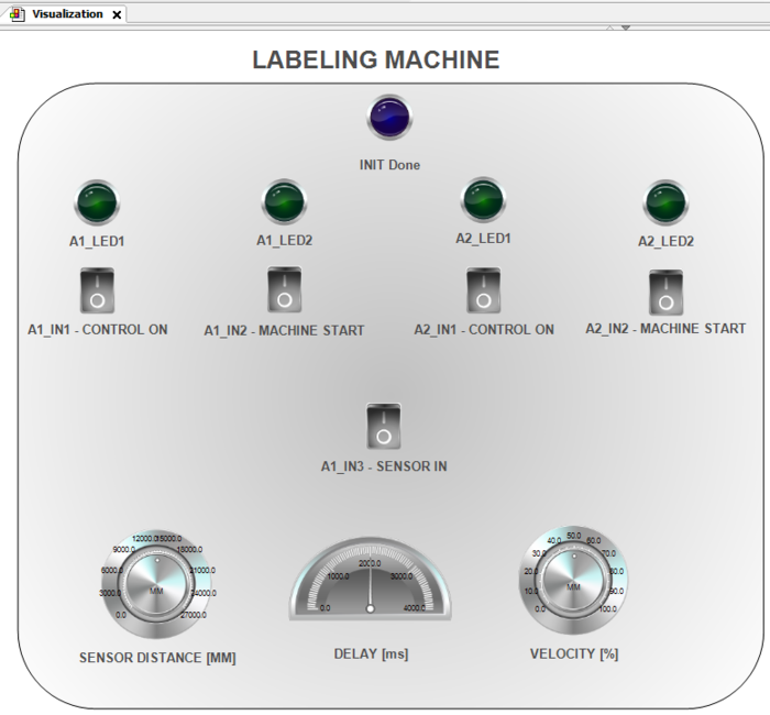
The program is controlled by a graphic interface:

When the startup process of softMC is done, the blue lamp is turned on.
The user can turn on and off Inputs 1 - 2 for each drive and watch their status in the green lamps.
The product sensor detection input can be turned on (Input3 of drive 1).
The distance, delay time and velocity are displayed by graphic meters.


