Master-Slave Connection
| Language: | English • 中文(简体) |
|---|
| IMPORTANT | |
| This entry is outdated and requires revision. |
Contents
Introduction
Master-Slave motion links the position of one axis (slave) to the position of another (master). The master axis is any axis controlled by the softMC or an external axis. External axes are connected to the softMC via the external encoder input on any of the drives controlled by the softMC.
There are two types of master-slave motion: gearing and camming. Gearing is used when the position of the slave must be proportional to the position of the master. Camming is used when the relationship is more complex. Camming allows you to specify a one-to-one mapping of the positions of the master and slave.
Master Sources
The master signal for master-slave motion is one of three sources:
- A physical axis controlled by the softMC.
- A simulated axis inside the softMC.
- An encoder signal connected to the external encoder input of a drive attached to the softMC.
The internal softMC clock produces an incremental pulse every SERCOS cycle. To set the master source of an axis, use MASTERSOURCE. For example, to set the master input for axis A2 to the position feedback of axis A1 enter:
A2.MasterSource = A1.PositionFeedback
This works whether A1 is a physical or simulated axis.
You can also use POSITIONCOMMAND (PCMD) as a source for gearing or camming. This eliminates the lag caused by the position error in the master axis. The negative side is the slave is following the command, rather than the actual position.
Many times, the master source needs to be an external encoder signal. This may be an encoder from a line-driven motor or from a servo motor controlled by an external device, such as a PLC or even another softMC. Sometimes the master source is not a motor. For example, you can use a pulse train as a master signal. In all these cases, the signal is connected to the external encoder input of one of the drives controlled by the softMC. The drives accept standard quadrature encoder signals as well as pulse trains. Refer to the installation manual for your drive for more information about the external encoder input.
After the external signal is connected, it can be assigned as the master source of any axis using the variable, POSITIONEXTERNAL (PEXT). For example, to set axis A2 to follow the external encoder input of axis A1, type:
A2.MasterSource = A1.Pext
For this function to work, the axis must be configured in SERCOS to run on telegram 7, and PEXT must be selected as one of the data elements communicated back from the drive.
If the axis has to be controlled, instead of adding a simulated master, it can follow an internal clock. This makes the master a type of TIMEPULSE. Set the GEARRATIO to a low value (less then zero) and increase its value step by step to avoid exceeding velocity limit.
For optimal performance, the master axis should have an axis number less than the slave axis. If the slave axis is A1 and the master axis is A2, an additional time cycle is inserted in the motion.
If the master velocity override is changed, the slave velocity is changed accordingly. In a relative move, the slave moves according to its new velocity override. VELOCITYOVERRIDE has no effect on the master signal for a slaved axis. It also has no effect on the gear ratio or cam table. VELOCITYOVERRIDE modifies the velocity of incremental moves added onto geared or cammed motion.
Gearing
When two axes are geared, the position command of the slave is proportional to the master signal as shown below.
Gearing works in both directions of master travel. The term, proportional, is applied loosely. The offset between the master and slave axes is saved at the time gearing is enabled and is maintained throughout gearing.
Enable Gearing
To enable gearing, set MASTERSLAVE to GEAR:
A1.Slave = GEAR 'Enable gearing
Enabling gearing during an absolute or relative move generates an error. An error is also generated if an attempt is made to enable gearing during camming. Incremental moves are allowed when gearing is enabled and during gearing.
Disable Gearing
To disable gearing, set SLAVE to OFF:
A1.Slave = OFF 'Disable gearing
When gearing is disabled, the velocity of the slave axis is decelerated to zero at the rate of <''axis''>.DECELERATIONMAX (DMAX). Disabling an axis does not automatically disable gearing. You do not need to enable gearing again when the axis is re-enabled. However, issuingJOG or STOP for the axis disables gearing.
STOP turns gearing off immediately. The velocity of the axis is decelerated to zero at the rate set by <''axis''>.DMAX. For JOG, gearing is disabled immediately and the movement is controlled by the JOG profile.
If the master axis' RTK (RealTime Kernel or software code) is executed before the slaves’ RTK, (i.e., if ?axislist displays the master before displaying the slave) and the master source is PCMD, there is no delay in execution. If the master source is a feedback, PFB or PEXT, there is a system delay of 1 SERCOS cycle time. If the slave RTK is executed before the master RTK, an additional delay of 1 cycle time is incurred.
Set the proportional constant between the master and slave with <''axis''>.GEARRATIO:
A1.GearRatio = 0.5 'Slave goes half the speed of master
GEARRATIO is a double-precision floating-point number that is set to less than zero to reverse the direction of the slave.
Incremental Moves
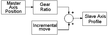
The softMC supports incremental moves with gearing. The profile of the slave axis is the sum of two profiles: the gearing profile and the profile of the incremental move:
You can use incremental moves with and without gearing. Issuing an absolute move with gearing enabled generates an error. If you issue STOP to a geared axis executing incremental moves, gearing is turned off immediately and the velocity commanded from gearing ramps to zero at <axis>.DECELERATIONMAX. However, the termination of the incremental move profile and subsequent launch of JOG is subject to <axis>.STOPTYPE.
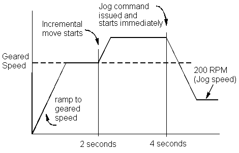
Issuing JOG when gearing with an incremental move is similar to issuing JOG with just gearing. The main difference is that the launch of the JOG profile is subject to <''axis''>.STARTTYPE. If STARTTYPE is IMMEDIATE (IMMED) or SUPERIMMEDIATE (SIMM), the jog begins immediately. The speed from the incremental move ramps up or down to the specified jog speed according to either <''axis''>.DEC or <''axis''>.ACC. If STARTTYPE is GCOM, SYNC or INPOS, the jog profile is delayed.
The following example issues JOG with an immediate start (STARTTYPE=IMMEDIATE).
Jog A1 100 TimeJog=5000
Sleep 2000
A1.StartType=IMMED
Jog A1 200
The resulting profile is:
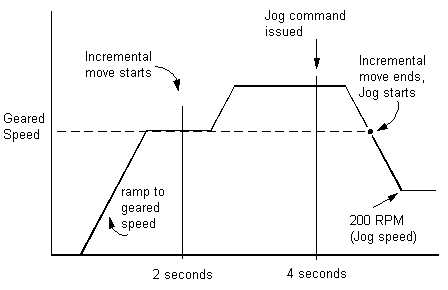
This next example shows the previous example, but with the starting after the incremental move is complete (STARTTYPE = GCOM):
Jog A1 100 TimeJog=5000
Sleep 2000
A1.StartType=GCOM
Jog A1 200
The resulting profile for this is:
Camming
Camming is an extension of gearing. It can be thought of as gearing where the gear ratio varies according to the master position. The master position, optionally runs through a gear ratio and drives the input to a cam table. The cam table is a list of point pairs which map the master position to the slave position. The output of the cam table provides the slave axis position.
The operation of camming looks like:
Key Features
The softMC camming features are:
Camming supports motion in both directions. The master runs indefinitely in either positive or negative direction without accumulation of error.
Cam tables are driven by an axis position command, an axis position feedback, or an encoder brought in through the external encoder input. It is driven by either physical or simulated axes.
Cam tables are two-dimensional. The points may be irregularly spaced. Linear interpolation is used between points.
Cam profiles do not need to return to the original position at the end of the profile.
Cam tables are calculated either off-line and stored, or on the fly.
Cams cycle either indefinitely or are specified to cycle a specific number of times.
Multiple cams are defined and linked together automatically.
The master position is processed through the master-slave gear ratio (GEARRATIO).
Issued incremental moves are summed with the cam profile to form the slave position command.
GEARRATIO
In camming, you set the proportional constant between the master and slave with <''axis''>.GEARRATIO. If GEARRATIO = 1, the table is matched one-to-one to the master axis. If it is less than one, the table is driven at a speed slower than the master is moving. For example, to run the table at half the speed of the master:
A1.GearRatio = 0.5 'Drive cam table at half speed
The master turns two units to drive the table one unit.
GEARRATIO is a double-precision floating-point number. To reverse the direction of the slave, enter the ratio as a negative number. Its value is changeable during camming, but it has to be done carefully to avoid a position jump in the slave value due to large differences between the old and new value.
Incremental Moves
With incremental moves to the slave, the profile from the incremental move is summed with the profile for gearing to form the slave position.
Cam Tables
A cam table is a list of master/slave point-pairs that define a one-to-one mapping of the master to the slave axis. You specify the number of point pairs. It may be as large or as small as the application requires. The following is a typical cam table:
CAM1.1 = (10, 20)CAM1.2 = (20, 40)CAM1.3 = (30, 60)CAM1.4 = (40, 80)CAM1.5 = (50, 100)
In cam tables, the position of both the master and slave are in the position units of the respective axes. The individual points in the table are given at irregular intervals. This is useful if the cam profile has long smooth sections and sharp turns. Irregular intervals allow you to use a few points for the smooth section and many for the sharp turns. Although the interval of master position is irregular, it must always be greater than zero. The master position must be monotonically increasing or decreasing in the cam table. The slave position is not limited by this requirement.
In the unusual case that the master position is located exactly on one of the master position points, the slave position is the corresponding point of the master/slave point-pair. When the master is located between two points, the softMC uses linear interpolation to calculate the position.
Cam tables are incremental in one aspect and absolute in another. Within the cam table, the positions are absolute. Suppose you want a cam table with 5 points with each point of the master separated by 10 units, and slave positions separated by 20 units. The table (with the assumed name CAM1) is:
CAM1.1 = (10, 20)CAM1.2 = (20, 40)CAM1.3 = (30, 60)CAM1.4 = (40, 80)CAM1.5 = (50, 100)
The master and slave positions are absolute within the table. This method is not a valid way of entering cam table items, but it is an illustration of the table entries. Creating cam tables is covered later.
Cam tables are incremental with reference to the start point. The start position in a cam table is always offset to the master and slave positions when the cam table is enabled. The operation of the table above is identical to the table below where the point pairs are adjusted to allow the first point to change from (10, 20) to (0, 0):
CAM1.1 = (0, 0)CAM1.2 = (10, 20)CAM1.3 = (20, 40)CAM1.4 = (30, 60)CAM1.5 = (40, 80)
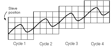
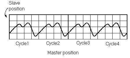
Cam tables can be specified to command net motion. The start and end points of the cam table are different. The reason cam tables are incremental or decremental with regard to starting points is to allow a cam table to generate net motion while allowing it to be called many times in succession. Consider the following graph that shows just such a cam table with net motion executed for four cycles:
Each successive cycle ratchets the slave position up. The starting position in the table cannot be equal to the actual slave position or the cam slave position (which is fixed in the cam table) and the actual slave position (which is ratcheting up each cycle) does not match for more than one cycle.
The distance to be moved is specified indirectly through the cam table data. The total displacement of one cycle of the master is the master position of the last point pair less the master position of the first, divided by GEARRATIO.
In many applications, you must ensure that this quantity is precise or the master appears to creep over time. The softMC uses double-precision math (16 digits of accuracy) for cam calculations. Use the softMC to calculate mathematical expressions to obtain the greatest possible precision. For example, if GEARRATIO=1:3, use the softMC to calculate the value rather than rounding a previously calculated value:
MasterGearRatio = 1/3 'Good: 1/3 accurate to 16 places

MasterGearRatio = 0.33333 'Poor: 1/3 accurate to 5 places
The net motion commanded to the slave is the slave position of the last point-pair less that of the first. If you do not want net motion in the slave, you must assign the slave positions of the first and last point-pairs to be identical.
At the point when camming is enabled, the softMC takes a snap-shot of the master position feedback, position or position external (depending on master definition), and slave position and offsets all entries in the cam table for the master and slave. cam tables are incremental with respect to the actual position of the axes at the time camming is started. For example, suppose a cam table starts at (0, 0) but when the camming is enabled, the master position is 1000 and the slave's position (PCMD) is -2000. Each point-pair in the table is implicitly adjusted by (1000, -2000) throughout the cam cycle.
After each cam cycle, the offset to the master and slave is adjusted by the softMC. The cam master position is adjusted for the difference between the master position at the starting and ending points. If the cam table has net motion, each subsequent cycle adds the net motion to the slave-commanded position.
Both the master and slave can be in rotary mode without affecting the camming operation.
Cam Cycles
One cam cycle is the operation of moving the master position feedback through an entire cam table. Instead of using master position feedback, you can use position or posistion external. At the end of a cam cycle, the cam ends or transitions to the next cycle. The next cycle simply repeats the current cam or is another cam. The number of times a cam is repeated is controlled by <cam>.CYCLES. Other cams are linked in automatically with NEXT and PREVIOUS.
When the master is moving forward, the cam position feedback counts up. The cycle ends when the master position is greater than the last entry in the cam table. Then, the cam moves to the next cycle. Similarly, when the master is counting down, the cycle ends when master PFB is less than the first entry in the table. The cam moves to the previous cycle. It all depends on whether the table is increasing or decreasing. If there is no NEXT (or PREVIOUS) cam cycle, camming is disabled and the slave axis stops.
Whether or not the cam cycle repeats, and the number of times it should repeat, is specified in <cam>.CYCLES. You can enter 1 to indicate that the cam runs once and does not repeat, -1 to indicate the cam runs indefinitely, or use a positive numberto indicate the number of times the cycle runs.
For example, suppose you want a cam to run four cycles as shown below:
You would use the following line:
CAM1.CYCLE = 4 ' Run cam1 four cycles
If you want a cam to run the same table an indefinite number of times, use:
CAM1.CYCLE = -1 'Run the cam indefinitely
When two cam tables are interconnected in a double-linked chain, only one cam table is active at a time. This enables changes in the other chained cam table by controlling the cycle time parameter of the active cam table. Setting its value to –1 results an infinity periodic of the active cam. After updating all the relevant values in the chained table, set the active table cycle to 1. At the end of the current period, the two tables are exchanged and the chained cam table is generated.
You can monitor the number of cycles run with <''axis''>.CAMCYCLE. When the master is moving forward, CAMCYCLE counts up. When CAMCYCLE reaches CYCLE, the axis transitions to the next cam, if there is one. Similarly, when the master is running backward and CAMCYCLE reaches 0, the cycle transitions to the previous cam, if there is one.
The softMC allows you to specify multiple cam tables at the same time. The maximum number of cam tables is 256. The softMC allows you to link cam tables together using two properties of the current cam table: NEXT and PREVIOUS. These properties allow automatic transition from one cam table to another without the accumulation of error in the master or slave positions.
To link one table to another, assign NEXT and PREVIOUS to the desired cam table. For example:
StartCam.Next = ForwardCam

StartCam.Previous = ReverseCam
The linking of the three cams (Cam0, Cam1, Cam2) is shown in the next figure.
Set NEXT and PREVIOUS independently. The NEXT and PREVIOUS pointers cannot be changed dynamically. The change takes place at the next transition of the cam table. If you do not want to link to another cam at the end of the current cam's cycle, set NEXT and PREVIOUS to NULL (0).
If you have linked cams, the cam cycle runs the number of times specified in CYCLES. For example, assume Cam1 is being driven by a forward rotating master. If CAM1.NEXT=CAM2 and CAM1.CYCLES=4, Cam1 cycles four times before transitioning to Cam2. Similarly, if the master is rotating backward and CAM1.PREVIOUS=Cam0, Cam1 cycles four times before transitioning to Cam0.
If the cam has run enough to exhaust the number of cycles and no cams are linked to the current cam, the axis automatically disables camming and decelerates at maximum deceleration to zero velocity.
Create Cam Tables
Cam tables contain the point-pairs that map the master position feedback to the slave position. cam tables are only a part of cams. Other properties of cams include CYCLE, NEXT and PREVIOUS. Only the table portion of cams are stored permanently in the softMC flash disk. The other properties are set during program operation.
There are two types of cam tables: static and dynamic. Static tables are built and stored in flash disk to be used later while dynamic tables are built at run time. You should choose a type based on your application.
Static Tables
Static cam tables are built offline and stored permanently in the softMC flash disk. They allow you to use advanced tools to graphically build and inspect the cam table, and do not take away from system processing resources at run time. Static cam tables are usually the best choice when the cam table does not change during normal operation.
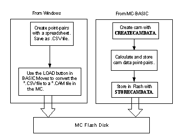
You can build static tables two ways. First, you can use Windows tools to build the table, then use softMC tools to convert and store the table. Second, you can build static cam tables inside the softMC. Both methods are shown in the next figure.
If you are using a static table, use the Windows-based tools. This method is simpler and you have more tools available with which to graph and analyze the cam table.
You can create point-pairs using windows applications such as a text editor, spread sheets (Excel), or mathematical programs (MatLab). For spreadsheets, create a new sheet with two columns and one row for each point-pair. Do not include a row for headings and do not include any other information within the sheet. The first element of each row is the master position. The second is the corresponding slave position. The master position must increase or decrease with each point-pair as long as it is monotonic. Its value cannot change directions (i.e., increase and then decrease) or stay the same.
When the table is complete, save to a Comma Separated Variable or .CSV file. This is a text file format with one line for each point-pair and commas between the master and slave values. For a five-point cam table, the .CSV file looks like:
10, 2020, 4030, 6040, 8050, 100
When you add the .CSV file to your project, ControlStudio converts it to a cam table and stores it in the softMC.
When building a cam table using MC-Basic, first globally allocate cam storage. Use Common Shared <var> as Cam:
Common Shared CAM1 as Cam
Here, CAM1 is used as the name. Replace CAM1 with any legal softMC name. The easiest way is to include this line in Config.Prg and reboot the softMC. The alternative is to enter this at the terminal window. Remember that the effect of this line persists only until the softMC resets.
Using MC-Basic, create storage for the table of point-pairs. First, select a task to calculate the point pairs and enter the following line in that task:
Program CamMaker
CreateCamData 5 CAM1
This allocates five data points for CAM1. Essentially two arrays (of size 5) are created that are named CAM1.MASTERDATA and CAM1.SLAVEDATA.
Calculate the point-pairs to use in MC-Basic. Build loops and iterate through the array. The array is 1-based and you receive an error if you go outside the bounds of this array. For this example, the points are simply loaded:
CAM1.MasterData[1]=10
CAM1.SlaveData[1]=20
CAM1.MasterData[2]=20
CAM1.SlaveData[2]=40
CAM1.MasterData[3]=30
CAM1.SlaveData[3]=60
CAM1.MasterData[4]=40
CAM1.SlaveData[4]=80
CAM1.MasterData[5]=50
CAM1.SlaveData[5]=100
Finally, store the table on the flash disk. If you use:
StoreCamData MyCam.Cam Cam1
This stores the cam as MyCam.Cam in flash memory. The name of the file follows the 8.3 format. The filename cannot have more than 8 characters in the main part and 3 characters in the extension. The cam data file must have the .cam extension This file can be loaded at any time using LOADCAMDATA.
If you created the cam storage (Common Shared <var> as Cam), delete it with:
DeleteCam Cam1
A cam table cannot be deleted if it is in use or if the task that it is attached to is loaded.
Dynamic Tables
Cam tables can be calculated dynamically. This allows you to build a cam profile based on events that occur during operation, such as the current position or speed of an axis. This process is identical to the process of creating a static cam table from MC-Basic except you do not place the data in flash. Instead, you use the cam table directly.
Operating Cams
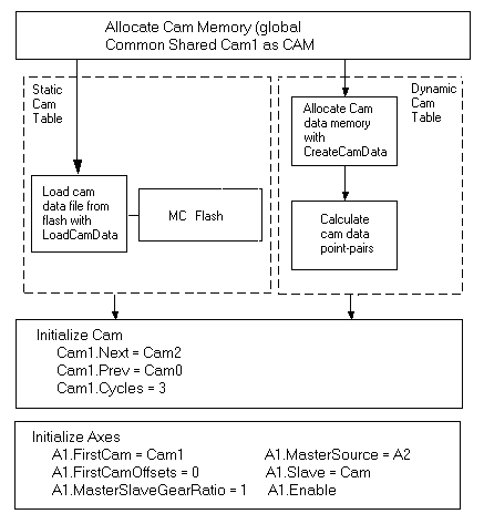
Now that you know the concepts of camming, you need to know the step-by-step process to use one. Throughout this section, CAM1 is our example. The entire process is shown in the figure below:
Step 1: Allocate Space Allocate space for the cam with Common Shared <var> as Cam. All cams are global, so this line must be located in Config.Prg. For example:
Common Shared CAM1 as Cam
Step 2: Load Cam Data This can be accomplished in two ways. For a static cam data array which has been calculated and stored in the softMC, use LOADCAMDATA:
LoadCamData MyCam.Cam CAM1
or dynamically calculate the cam. This is a two step process. First, create space for the data array and then fill that space. For example, for a five element array, you enter:
CreateCamData 5 CAM1

CAM1.MasterData[1]=10

CAM1.SlaveData[1]=20

CAM1.MasterData[2]=20

CAM1.SlaveData[2]=40

CAM1.MasterData[3]=30

CAM1.SlaveData[3]=60

CAM1.MasterData[4]=40

CAM1.SlaveData[4]=80

CAM1.MasterData[5]=50

CAM1.SlaveData[5]=100
This is similar to building a static cam table. The difference is that this cam table is never stored to or loaded from flash.
Step 3: Initialize Other Elements Initialize other elements of the cam:
CAM1.Next = CAM2

CAM1.Previous = CAM0

CAM1.Cycles = 3
Step 4: Initialize the Axis Initialize the elements of the axis related to camming. Set FIRSTCAM to the first cam the axis follows:
A1.FirstCam = CAM1
Set the master position within the cam at the point where you wish to start. For example, you may have a cam table where the master position goes from 0 to 100.00, but the correct starting position for the cam might be 33.333, so you enter:
A1.FirstCamOffset = 33.333
FIRSTCAMOFFSET must be within the range of the master position. Remember that FIRSTCAMOFFSET defaults to 0. If the master range does not include zero, an error is generated if you do not set FIRSTCAMOFFSET.
Set GEARRATIO and name the source of the master signal:
A1.GearRatio = 1.00

A1.MasterSource = A2.PFB
Finally, set SLAVE to CAM:
A1.Slave = CAM
Step 5: Enable the Axis At this point, camming is enabled. However, you must enable the drive to see motion:
A1.Enable = ON
Camming cannot be enabled if the axis is in a relative or absolute move, or during STOP. Enabling camming when gearing is enabled or when an absolute move is being executed generates an error. Disabling or enabling the drive does not affect whether gearing is enabled.
To disable camming, set SLAVE to OFF:
A1.Slave = OFF 'Disable camming
When camming is disabled, the velocity of the slave axis is decelerated to zero at the rate of <''axis''>.DECELERATIONMAX (<''axis''>.DMAX). Issuing JOG or STOP for the axis disables camming. Issuing STOP turns camming off immediately. The velocity of the axis is decelerated to zero at the rate set by <''axis''>.DECELERATIONMAX.
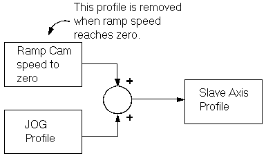
If JOG command is issued, camming on that axis is disabled immediately and the cam profile ramps to zero at the rate, <''axis''>.DEC. The JOG profile ramps up at the rate specified by <''axis''>.ACC. For a short time, the axis profile is the sum of these two profiles as shown below.
After the camming profile goes to zero, the profile is controlled wholly by the JOG profile. Disabling the master or slave does not disable camming. Camming remains active and the slave position is commanded accordingly, when re-enabled. A fault is generated when the drive is re-enabled if the distance between the slave position and the command from the cam table is greater than POSITIONERRORMAX. Be cautious when re-enabling a cammed slave axis if a large position error exists. The motor rapidly upon enable to immediately correct this error.
Step 6: Read Dynamic Information There are numerous read-only properties regarding the operation of the cam.
Axis Properties
<''axis''>.ACTIVECAM provides the name of the cam being executed by that axis.
Cam Properties
<cam>.CAMCYCLE provides the number of cycles the cam has executed. If the cam master is moving forward, the current cam ends at the completion of the cycle where CAMCYCLE=CYCLE.
When the cam master is moving backward, the current cam ends at the completion of the cycle where CAMCYCLE=0.
<cam>.CAMINDEX provides the current index within the current cam table. For example, if there are 100 points in the table and the cam is half complete, CAMINDEX=50.
<cam>.MASTERDATA is used with CAMINDEX to provide the value of the master position of the current index within the cam. For example, if the current cam table master position range is -10 to 10 and the position is in the middle of the range, CAM1.MASTERDATA [CAMINDEX]=0.00.
CAM1.MASTERDATA[CAMINDEX] is not equivalent to the position of the master signal (<''axis''>.PFB) because cams are incremental with respect to starting position.
<cam>.SLAVEDATA used with CAMINDEX to give the value of the slave position for the current index of the cam. As with CAMVALUE, CAM1.SLAVEDATA[CAMINDEX] is not equivalent to <''axis''>.PCMD because the two may be offset from each other.
Simulated and Master-Slave Axes
Simulated axes are used to enhance machine control. They typically are with gearing and camming. Three common uses are:
- To act as fixed speed masters for slaved axes.
- To monitor physical axes.
- To synchronize slaved axes.
Fixed-Speed Masters
The most common use for a simulated axis is as a fixed-speed master axis for geared or cammed axes. This is used for testing or as part of normal operation. The simulated axis is normally set to a fixed speed using JOG. Slave axes are driven without a physical motor. For example, if you want to view a cam table, you can use a simulated axis running at a fixed speed. In a sense, the simulated axis provides the ideal condition where the master speed is precisely fixed. This can allow you to fine-tune cams and carefully inspect the synchronization of geared axes.
Fixed-speed simulated axes and cams are combined to allow you to produce virtually any profile you need for a machine. You need only load the profile, cam table and drive the axis with a fixed-speed simulated axis.
Monitor Physical Axes
Simulated axes are used to monitor physical axes for machine control by slaving a simulated axis to a physical axis and monitoring the position and/or velocity of the simulated axis. For example, if you slave a non-rotary simulated axis to a rotary physical axis, you can monitor the total distance the physical axis has traveled because any variable from a simulated axis can be used to fire events. You can generate events based on the simulated axis. The position feedback of a simulated axis can drive a Programmable Limit Switch (PLS) to add more monitoring flexibility.
Synchronize Slave Axes
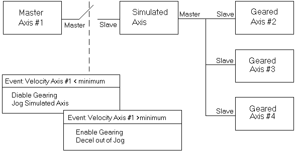
Many machines have multiple slaved axes that are controlled as a group. Normally, synchronization is maintained when these axes share a single physical axis as a master. However, on some machines, there are special modes of operation where a physical axis cannot provide all the necessary functions. Consider a machine where a minimum speed must be maintained on the slave axes even if the master axis stops. In this case, you can insert a simulated axis between the physical master and slave drives. To do this, slave a simulated axis to the physical master and then slave the other axes to the simulated axis. Use events to tell when the physical axis is above or below the minimum and use JOG to keep the simulated axis above the desired minimum to keep the slave axes moving even if the physical master stops.
For example:
Program

OnEvent Vel_Below_Min PseudoAxis.Vcmd < 100

Jog PseudoAxis 100

‘This indirectly turns gearing off

End OnEvent

OnEvent Vel_Above_Min PseudoAxis.Vcmd >= 100

PseudoAxis.Slave=Gear

End OnEvent

Attach PseudoAxis

EventOn Vel_Below_Min

EventOn Vel_Above_Min

While 1

Sleep 100

End While

End Program
The following figure shows this process.


