How To Assign A New Robot Model To RoboDK
Contents
- 1 Introduction
- 2 Procedure
- 3 Appendices
Introduction
The main purpose of this section is to teach the user, step by step, how to assign a new robot to RoboDK by using STEP files.
The primary goal is to create several STEP files that separately contains the robot's joints parts out of the SolidWorks files.
Note: every file must contain all of the robot's parts that move together around the same axis.
It's preferred to receive all files separately, but mostly the hole robot will be sent as one file.
Procedure
Step 1: Dividing The SolidWorks Assembly
SolidWorks
- Open the file with SolidWorks.
- Figure out the structure of the robot.
- check if the main assembly is actually divided to the needed sub-assemblies of joints and base.
- for the files to be as light as possible, so RoboDK can integrate the joints and perform easily, delete all unnecessary components for the joints graphics (inner components, inner bolts, small and unwanted graphics, etc.).
Note: If not divided correctly to the appropriate sub-assemblies, the following action must be taken:
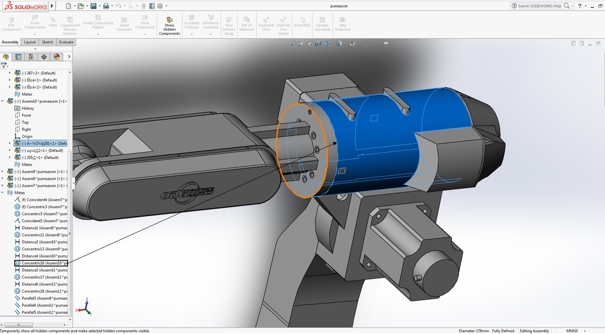
- Mark all the parts and sub-assemblies that move around the same axis and unite them to the same sub-assembly.
- Save and name that sub-assembly with the appropriate joint name (base, joint 1, joint 2).
- The example above shows joint 2 sub-assembly after assigning the servo motor part, that controls joint 3, under that sub-assembly because it moves with joint 2 (around Y axis).

Step 2: Calibrating The Robot's Orientation
SolidWorks
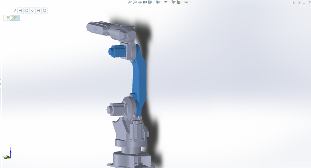
- Now, the sub-assemblies are corrected as the right base and joints. To ensure proper visualizing with RoboDK, calibration of orientation must be done.
- In SolidWorks, the default Isometric orientation is that the base is parallel to the XZ plane.
- Change the base orientation to be parallel to the XY plane.
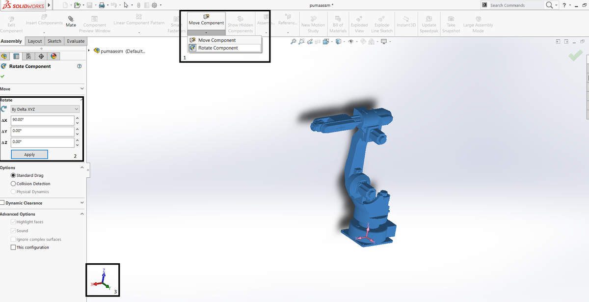
- Mark all of the components. Press 'Move Components' --> 'Rotate Components'.
- Choose the Rotate tab and change the orientation of the robot as explained above, afterwards press Apply.
- Verify the changes according to the orientation of the robot relatively to the coordinate system.

Step 3: Centralizing Base And Joints
SolidWorks
- The main assembly origin must unite with the base assembly origin, and so all the other assemblies.
- Centralizing the robot relatively to it's base:
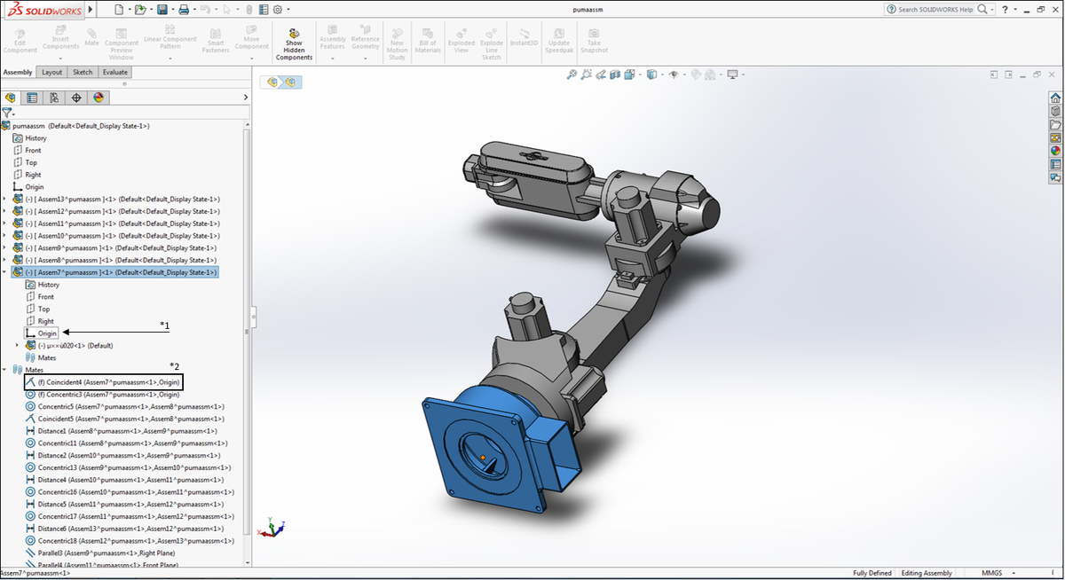
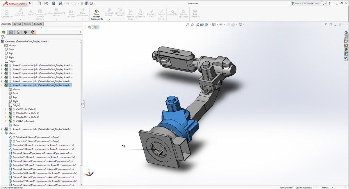
- Define the base origin as the main assembly origin
- Centralize all joint's sub-parts that supposed to be centralized, relatively to the defined base center.
- Note: (*1) Same origin as the main assembly. (*2) Unite both origins (base and main assembly).


Step 4: Defining The Connections Between The Various Parts
SolidWorks
- Define all parts in every sub-assembly separately:
- Every sub-assembly has parts that integrate differently with one another. Some are concentric, some are linked and some have fixed distance between them, all of this features must be defined correctly if they are not already defined so.
- Define the connections above for every possible part in the sub-assembly (including trademarks/symbols and so forth).
- Make sure they're parallel to the right plane and move around the right axis.
- Example:
-
- Note: The Concentric mate between joints 3 and 4.

Step 5: Saving The Files
Windows
- Open every sub-assembly as a separate SolidWorks file.
- Example
- Example

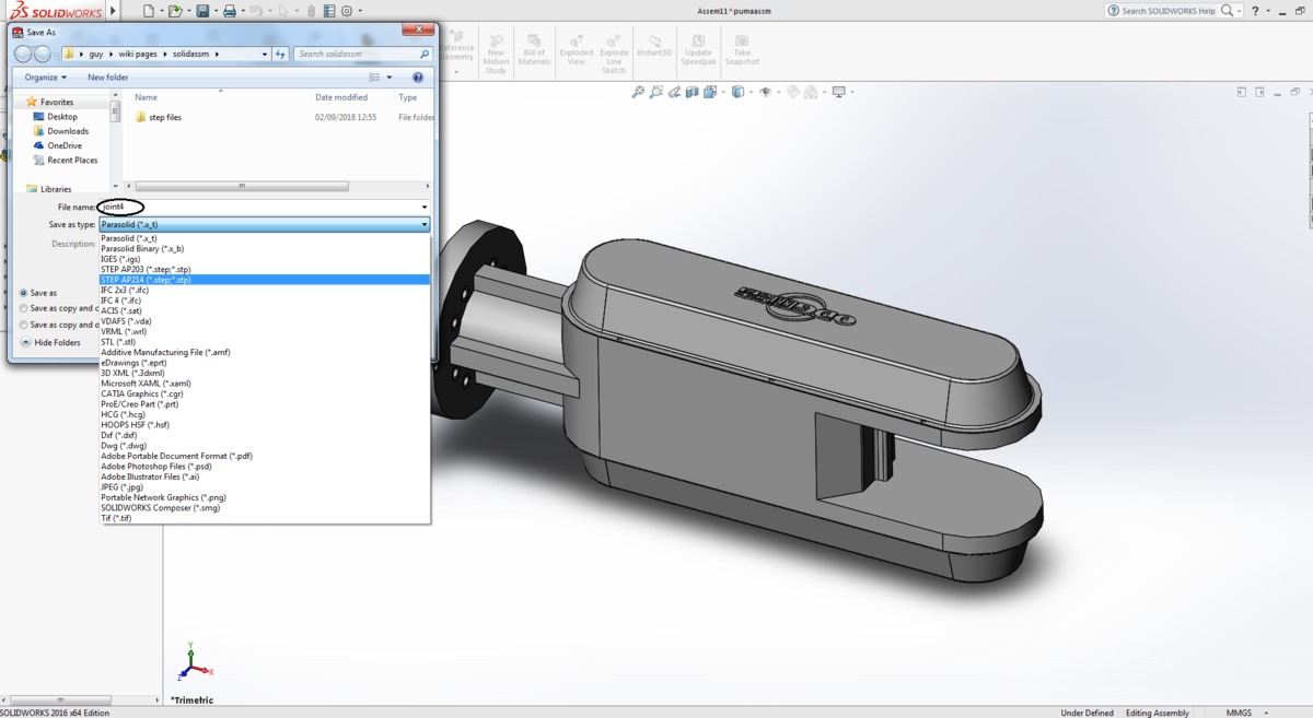
- Name the sub-assembly and Save it as a STEP.AP214 file.
- Example
- Example

- Note: Other extensions might not work with RoboDK.
Step 6: Defining The Robot With RoboDK
RoboDK
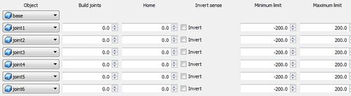
- Open the files with RoboDK. Define the robot.
- Press 'Utilities' --> 'Model Mechanism or Robot', the following window will appear.
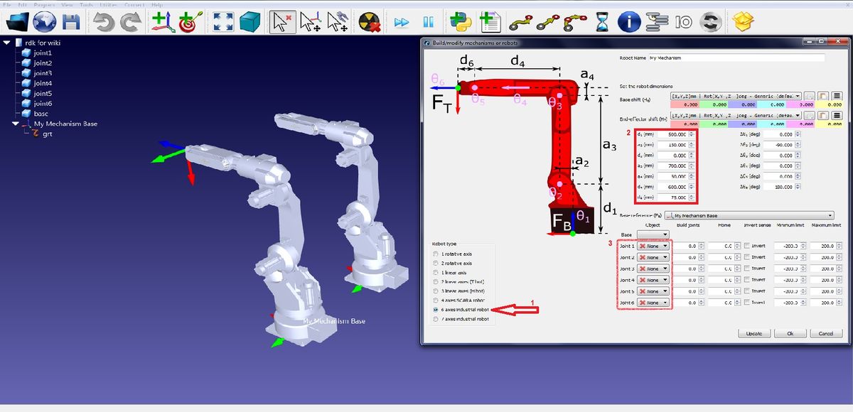
- Choose the type of robot.
- Measure the robot with SolidWorks and assign the appropriate measures for every link of the robot.
- Choose the correct graphics for every link from the sub-assemblies created in step 5.
- Press 'Utilities' --> 'Model Mechanism or Robot', the following window will appear.


Step 7: TroubleShooting
TroubleShooting Step 3
SolidWorks
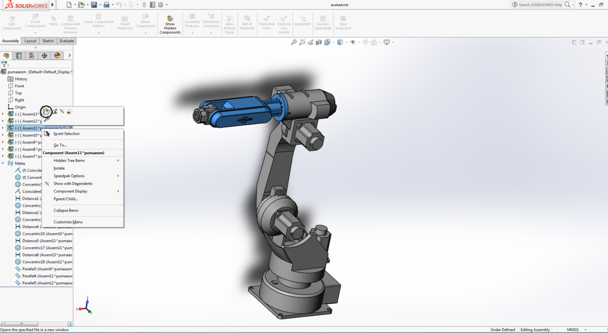
- If the origin is still in an unwanted position, define the problematic sub assembly as a new sub assembly.
- press right 'click' on the wanted sub assembly --> press 'Form A New Sub Assembly'.
- the origin should appear as the origin of the main assembly
TroubleShooting Step 5
SolidWorks
- If the sub assembly open's in a different orientation, rotate it to the desired orientation (follow Step 2).
TroubleShooting Step 6
RoboDK/SolidWorks
- Try to move all joints separately. If they do not move as they should, go back to step 6.3 and try to change the values of the various joints.
- If the robot is still acting not as expected, go back to step 6.2 and check the measures again.
another option is to go back to step 4 and check if every part is defined properly.
