DELTA robot
| Language: | English • 中文(简体) |
|---|
Contents
DELTA robot model
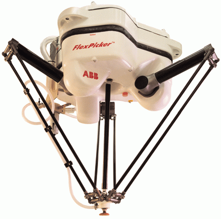
The DELTA robot is a four – degrees of freedom parallel robot of the following configuration:
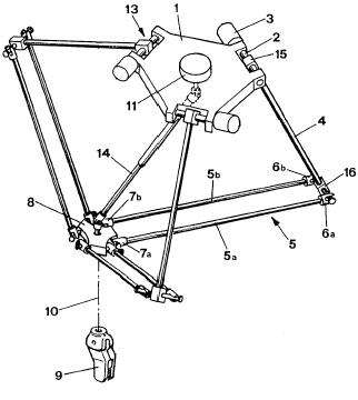
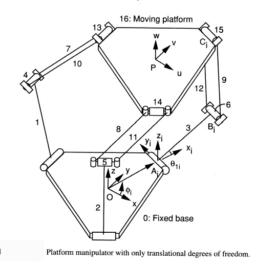
The basic idea behind the Delta parallel robot design is the use of parallelograms. A parallelogram allows an output link to remain at a fixed orientation with respect to an input link. The use of three such parallelograms restrains completely the orientation of the mobile platform which remains only with three purely translational degrees of freedom. The input links of the three parallelograms are mounted on rotating levers via revolute joints. The revolute joints of the rotating levers are actuated in two different ways: with rotational motors or with linear actuators. Finally, a fourth leg is used to transmit rotary motion from the base to an end-effector mounted on the mobile platform.
WIPO patent issued on June 18, 1987 (WO 87/03528):
“The device comprises a base element (1) and a movable element (8). Three control arms (4) are rigidly mounted at their first extremity (15) on three shafts (2) which may be rotated. The three assemblies each formed by a shaft (2) and an arm (4) are the movable parts of three actuators (13) of which the fixed parts (3) are integral with the base element. The other extremity (16) of each control arm is made integral with the movable element through two linking bars (5a, 5b) hingedly mounted on the one hand to the second extremity (16) of the control arm and, on the other hand, to the movable element. The inclination and the orientation in the space of the movable element remain unchanged, whatever the motions of the three control arms may be. The movable element supports a working element (9) of which the rotation is controlled by a fixed motor (11) situated on the base element. A telescopic arm (14) connects the motor to the working element.”
Also: (US 4,976,582), and (EP 0 250 470).
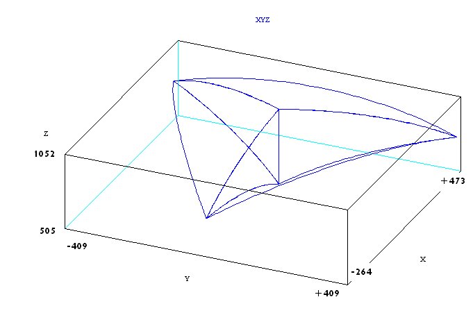
DELTA Work-Space
The Delta kinematics works with points of the XYZR robot type(X, Y , Z and Roll) where the first three coordinates are always expressed in millimeters and the roll angle in degrees.
The DELTA WORLD workspace is limited by joint limits and the following auxiliary cartesian boundaries, available for the user:
- RMAX – maximum radius of a cartesian point (), no points beyond this radius are allowed.
- RMIN - smallest radius of a cartesian point (). No points inside this radius are allowed.
- ZMIN – z coordinate of the “lowest” robot position. No points below this plane are allowed.
Robot configurations
Delta robot has no configuration flags, there is always one unique solution of the inverse kinematics problem. This further means that the configuration arguments in inverse kinematics function ToJoint have no influence on the result. Also Cartesian movements like MOVES, CIRCLE or PASS THROUGH are not influenced by any of the command configuration flags (acmd, ecmd, wcmd), the motion will be the same independent of the value of any of these flags.
Singular points
Delta robot, contrary to the open-kinematics chain robot has no singular joint positions where the joint velocities tend to infinity but there are so called “direct kinematics singularity” where the stiffness of the robot is significantly reduced.
Case when the upper arm linkages are parallel to each other. At this singular configuration manipulator can not resist any force applied in the plane of moving platform.
Another singular position which in is more a theoretical in our case is the so called direct kinematics singular configuration,in which all the upper arm linkages are in the plane of the moving platform. At such a configuration, the manipulator actuators can not resist any force applied to the moving platform in the z-direction.
This case is possible only when which in our case is not fulfilled!
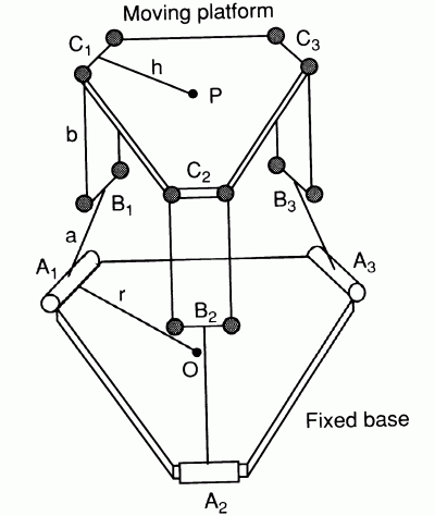
Geometric parameters of the DELTA robot
For DELTA family of robots we have:
| |
|
|
| |
|
|
| |
|
|
| |
|
|
| |
|
|
The above parameters of link matrix property of the robot must be filled-in in the robot’s setup file. In order that the system accepts the above setup the “configgroup” command must be executed. The model is assuming that the three base motors are rotated for exactly 120 degrees. Also it has been assumed that all three lags are of the same dimensions. The WORLD coordinate system is based in the center of the motor plane. Note that only the above set of parameters affects the robot geometry, the rest of the link[][] and axis[][] values do not influence the robot geometry in any way and are not affected (changed) by configgroup command or any other robot command.
Typical DELTA poses
Farthest (highest) reachable Z coordinate and the maximum joint angle.
Closest (lowest) reachable Z coordinate and the maximum joint angle.
If then the following is true (not applicable in our case):
“Zero” position, for
Having a robot with following geometry:
| |
|
|||
| |
|
|
| |
| |
|
|
| |
| |
|
|
| |
| |
|
|
|
Test:
-->?ToCart({0,0,0,0})
#{-5.68434e-14 , 0 , 505.569 , 0}
-->?toCart({106.87,106.87,106.87,0})
#{-7.10543e-15 , 0 , 1052.43 , 0}
-->
Orientation Angle
The DELTA kinematics has only one orientation angle (roll) it is directly (one-to-one) driven by the fourth motor. The value of the WORLD roll angle equals always to the fourth joint position limited (wrapped) to angle values between [-180, 180]. Orientation interpolation is determined by the OrientationFollwing flag. In the case of DELTA robots joint and world angles are directly related and therefore we have only two options of the OrientationFollowing flag:
- Take the longer path between initial and final roll angle: OrientationFollowing flag equals 2 or 3
- Take the shorter path between initial and final roll angle: OrientationFollowing flag equals 0 or 1

