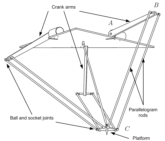
On a Delta robot the mechanical connection between the platform (point C) and the crank arm (Point B) is realized by a pair of parallelogram rods.
The ball and socket joints at B and C can only carry a limited force, which is push/pull force of the rods.
If the maximal force of the ball joints is exceeded, robot arms can hang out which leads to destruction of the robot.
Because of kinematic structure of Delta robots rod forces depend on position, acceleration and moving direction.
A physical model is needed to precompute rod forces for start/target positions and limit acceleration/deceleration according to maximal allowed forces.
Physical model
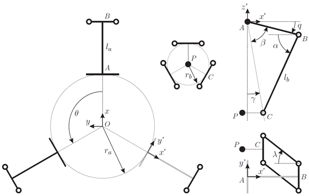
Relevant kinematic values
This rod forces model is based on the inverse dynamic model developed by IWF (File:Inverse kinematics and inverse dynamics for Delta - IWF report.pdf).
The actuating joint torques Failed to parse (MathML with SVG or PNG fallback (recommended for modern browsers and accessibility tools): Invalid response ("Math extension cannot connect to Restbase.") from server "https://en.wikipedia.org/api/rest_v1/":): {\displaystyle \tau_i}
are considered as known.
The coordinate system used by IWF differs from that used by Servotronix (Y and Z directions are inverted).
In this model the IWF coordinate system is used.
The transformation from and into Servotronix coordinate system is done by IDM implementation.
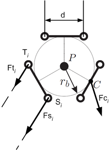
Forces at crank arms
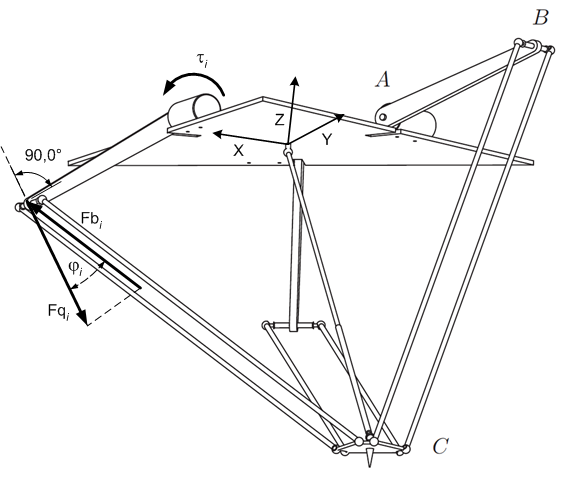
Forces at crank arms
The direction unit vector of the force  points perpendicularly to the crank arm:

The actuating joint torques  comprise load torque, friction torques, gravity compensation torque and dynamic torque (inertia):

The absolute value of  is then:

The direction of the parallelogram rods is the connection between points C and B:

The direction unit vector of the force  is parallel to the parallelogram rods:

The angle between and is obtained by using dot product definition:

The absolute value of is computed as:

Forces at the platform
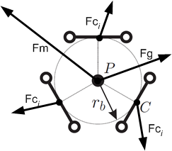
Forces at platform
The inertia of the parallelogram rods cannot be neglected.
Therefore the forces at point C are less then forces at point B.
The inertia force is proportional to the Cartesian acceleration vector:

Gravity force points downward:

Direction of  is identical to :

The unknown value of force is expressed by a variable:

The sum of all forces affecting at the platform is equal zero:

The unknown values of  are obtained by solving the linear equation system (7).
Torques at the platform
Torques at the platform
The rod forces do not affect at the platform's center of mass and therefore cause load torques which are compensated by the parallelogram structures.
These compensation torques produces additional forces in the parallelogram rods and have to be modeled as well.
Load torques are obtained by considering resultant rod forces at point C:

For the computation of compensation torques of both parallelogram rods are handled separately:

The compensation torques occur because the both rod forces are different:

The force difference of the both parallelogram rod forces is not known in first step.
It is expressed by a variable  :
:

For the compensation torques follows:

The addition of all load and compensation torques must be equal zero:

The unknown variables can be obtained by solving the linear equation system:

Parallelogram rod forces
Because  are unity vectors, the variables represent the differences of the both rod forces.
The absolute value of the bigger rod force is then:
are unity vectors, the variables represent the differences of the both rod forces.
The absolute value of the bigger rod force is then:

Load capacity reduction due to parallelogram shift
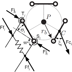
Parallelogram shift
The half-bowls of the ball and socket joints are held by a spring.
For the load capacity of the joint only the force components are relevant, that are perpendicular to the rods.
When the parallelogram is shifted the perpendicular forces become less and therefore the load capacity decreases.
To obtain the shift angle an intermediate step is needed:

The reduction factor of the joint's load capacity is then:
- Failed to parse (MathML with SVG or PNG fallback (recommended for modern browsers and accessibility tools): Invalid response ("Math extension cannot connect to Restbase.") from server "https://en.wikipedia.org/api/rest_v1/":): {\displaystyle Rs_i = \cos \sigma_i = \sin \xi_i = \sqrt{1 - \cos^2 \xi_i} \qquad \mathrm{(12)} }
Limitation of acceleration/deceleration
To set appropriate acceleration and deceleration values for a given straight motion it is adequate to test only the start and target points.
The acceleration rates at start point respectively the deceleration rate at target point are computed as quotient of maximal allowed rod force and the computed rod force:
- Failed to parse (MathML with SVG or PNG fallback (recommended for modern browsers and accessibility tools): Invalid response ("Math extension cannot connect to Restbase.") from server "https://en.wikipedia.org/api/rest_v1/":): {\displaystyle Ra = \min_i \frac {Fr_{max} \cdot Rs_i} {\left | \overrightarrow{Fr}_i \right |} \qquad \mathrm{(13)} }
Parameters
The only model parameter Failed to parse (MathML with SVG or PNG fallback (recommended for modern browsers and accessibility tools): Invalid response ("Math extension cannot connect to Restbase.") from server "https://en.wikipedia.org/api/rest_v1/":): {\displaystyle Fr_{max}}
can only be obtained by incrementally increasing (trial and error).


