Difference between revisions of "Robot Kinematics Models"
(→Cartesian coordinates and Euler Angles) |
(Added a comment about default point type) |
||
| (7 intermediate revisions by 2 users not shown) | |||
| Line 1: | Line 1: | ||
| − | {{Languages|Robot_Kinematics_Models}} | + | {{Languages|Robot_Kinematics_Models}} <div class="noprint" id="BackToTop" style="background-color:; position:fixed; bottom:32px; left:95%; z-index:9999; padding:0; margin:0;"> |
| − | <div | + | |
| − | <span style="color:blue; font-size:8pt; font-face:verdana,sans-serif; border:0.2em outset:#ceebf7; padding:0.1em; font-weight:bolder; -moz-border-radius:8px; "> | + | <span style="color:blue; font-size:8pt; font-face:verdana,sans-serif; border:0.2em outset:#ceebf7; padding:0.1em; font-weight:bolder; -moz-border-radius:8px;">[[File:TOP2.png|50px|TOP2.png|link=#top]]</span></div> |
| − | [[ | ||
= Introduction = | = Introduction = | ||
| + | |||
This document was written in accordance to the Kinematics proposal document received as an additional development request. <!-- Following the proposal, this document is divided according to the development phases: --> | This document was written in accordance to the Kinematics proposal document received as an additional development request. <!-- Following the proposal, this document is divided according to the development phases: --> | ||
| − | + | ||
| − | * PUMA Kinematics | + | *PUMA Kinematics |
| − | * DELTA Kinematics | + | *DELTA Kinematics |
| − | * Tool, base and compound operator | + | *Tool, base and compound operator |
New kinematics models of PUMA and DELTA robots are made always keeping what has been implemented for SCARA robots. Therefore if not explicitly stated different, all robotics features that were developed and implemented for the SCARA model will be available for the two models also. Therefore all the capabilities, methods and definitions of the features are common to all three models. The common robotics features for the above robots are: | New kinematics models of PUMA and DELTA robots are made always keeping what has been implemented for SCARA robots. Therefore if not explicitly stated different, all robotics features that were developed and implemented for the SCARA model will be available for the two models also. Therefore all the capabilities, methods and definitions of the features are common to all three models. The common robotics features for the above robots are: | ||
| − | * Straight-line motion | + | *Straight-line motion |
| − | * Circular movements | + | *Circular movements |
| − | * VIA (Pass-Through) movements. | + | *VIA (Pass-Through) movements. |
| − | * Continuous-Path – blending. | + | *Continuous-Path – blending. |
| − | * Conveyor tracking (Moving Frames). | + | *Conveyor tracking (Moving Frames). |
These features are not described in this document. | These features are not described in this document. | ||
| + | |||
| + | | ||
= Overview = | = Overview = | ||
| + | |||
This document describes a general kinematics implementation in the softMC system with the following kinematics models (and growing): | This document describes a general kinematics implementation in the softMC system with the following kinematics models (and growing): | ||
| − | * SCARA kinematics of '''4''' degrees of freedom. | + | *SCARA kinematics of '''4''' degrees of freedom. |
| − | * PUMA kinematics of classical PUMA robots of '''6''' degrees of freedom. | + | *PUMA kinematics of classical PUMA robots of '''6''' degrees of freedom. |
| − | * DELTA kinematics of DELTA parallel robots of '''4''' degrees of freedom. | + | *DELTA kinematics of DELTA parallel robots of '''4''' degrees of freedom. |
| − | * | + | *TARM kinematics of SpeedPicker robots of '''4''' degrees of freedom. |
| − | * USER kinematics for general user-defined robot kinematics of up-to '''6''' DOF systems. | + | *USER kinematics for general user-defined robot kinematics of up-to '''6''' DOF systems. |
| + | |||
== Definitions == | == Definitions == | ||
| − | * '''DOF''' – “degrees of freedom” of a robot | + | *'''DOF''' – “degrees of freedom” of a robot. In a serial robot it is usually the same as the number of motors in the robot. |
| − | * '''DH''' – Denavit Hartenberg parameters of robot describing robot geometry set of | + | *'''DH''' – Denavit Hartenberg parameters of the robot describing robot geometry set of (θ<sub>i</sub>, α<sub>i</sub>, a<sub>i</sub>, d<sub>i</sub>) numbers for each robot segment. |
| − | * '''“Tool-Center- | + | *'''“Tool-Center-Point (TCP)” - '''point on the last robot segment. By default it is in the center of the flange to which a gripper is mounted. Its coordinates can be displaced by the tool property as described below. |
| − | * In the whole of | + | *In the whole of this page we use term “'''point'''” for a vector describing the position and orientation of the robot’s TCP. The first part if this vector contains the cartesian coordinates of the TCP, while the second part describes its orientation. Depending on the robot type, the point can be an element of different vector spaces (such as two, three, six dimensional). |
| − | * A '''“location”''' is softMC data-type containing cartesian coordinates of a point. | + | *A '''“location”''' is a softMC data-type containing cartesian coordinates of a point. |
| − | * A '''“joint location”''' or '''“joint” '''is softMC data-type containing joint coordinates of a point. | + | *A '''“joint location”''' or '''“joint” '''is a softMC data-type containing joint coordinates of a point. |
= Coordinates Systems = | = Coordinates Systems = | ||
| − | |||
| − | |||
| − | + | == Cartesian coordinates and Euler Angles == | |
| − | |||
| + | In this section a method of robot point definition is shown. The presented method is given for a six-dimensional space defining both position and orientation, each having three degrees of freedom. For systems with more or less dimensions other coordinates systems will be used. | ||
| + | Each robot is defined by two properties. The first is the group model (SCARA, PUMA, DELTA, etc.). The actual robot model of a group can be queried using the [[MC-Basic:robot.TYPEOF|TYPEOF]] property. The second property is the point type. A robot of a specific model might have several available point types. For example, the SCARA robot (model = 4) has two point types: XYZ and XYZR. If the point type is not declared when the robot is defined, its default point type will be used (written in bold text in the table below). Whenever a motion is issued for a particular robot, its appropriate point type must be used. | ||
| − | {{robot_model_table}} | + | The following table lists the available robot models and their point types: {{robot_model_table}} |
| − | |||
| − | |||
| − | |||
== Examples == | == Examples == | ||
| − | |||
=== PUMA robot definition === | === PUMA robot definition === | ||
| − | |||
'''common shared ''puma'' as group axnm = a1 axnm = a2 axnm = a3 axnm = a4 axnm = a5 axnm = a6 model = 2''' | '''common shared ''puma'' as group axnm = a1 axnm = a2 axnm = a3 axnm = a4 axnm = a5 axnm = a6 model = 2''' | ||
| + | A location of PUMA robot: '''common shared ''lct'' as location of XYZYPR''' | ||
| − | |||
| − | |||
| − | |||
| + | === DELTA robot definition: === | ||
'''common shared ''delta'' as group axnm = a1 axnm = a2 axnm = a3 axnm = a4 model = 6''' | '''common shared ''delta'' as group axnm = a1 axnm = a2 axnm = a3 axnm = a4 model = 6''' | ||
| + | A location of DELTA robot (with default point type XYZR): '''common shared ''lct'' as location of XYZR''' | ||
| − | + | | |
| + | === XYZYPR vs. XYZR === | ||
| − | |||
The XYZYPR token for PUMA stands for: X-Y-Z-Yaw-Pitch-Roll coordinates and the XYZR for SCARA and DELTA robots stands for X-Y-Z-Roll. In both cases the roll angle defines the same thing - it is the angle of rotation about Z-axis. This is to be remembered later when the compound operator is defined then the following relation is true: | The XYZYPR token for PUMA stands for: X-Y-Z-Yaw-Pitch-Roll coordinates and the XYZR for SCARA and DELTA robots stands for X-Y-Z-Roll. In both cases the roll angle defines the same thing - it is the angle of rotation about Z-axis. This is to be remembered later when the compound operator is defined then the following relation is true: | ||
| + | | ||
'''X,Y,Z, ,Roll corresponds to X,Y,Z,Roll with <u>Yaw & Pitch equals zero.</u>''' | '''X,Y,Z, ,Roll corresponds to X,Y,Z,Roll with <u>Yaw & Pitch equals zero.</u>''' | ||
| − | |||
Cartesian coordinates describe robot locations defining position and orientation of the declared robot tool center point. A location can be expressed in at least three ways representing all 6 degrees of freedom encountered in the cartesian space: | Cartesian coordinates describe robot locations defining position and orientation of the declared robot tool center point. A location can be expressed in at least three ways representing all 6 degrees of freedom encountered in the cartesian space: | ||
| + | | ||
| − | * X Y Z Yaw Pitch Roll | + | *X Y Z Yaw Pitch Roll |
| − | * Homogenous transformation matrix | + | *Homogenous transformation matrix |
| − | * X Y Z Quaternion | + | *X Y Z Quaternion |
Common to all methods is the duality between location and transformation. Note that cartesian location gives coordinates of the tool center point which can be always interpreted as a transformation form the WORLD base point (space origin) to the tool center point. | Common to all methods is the duality between location and transformation. Note that cartesian location gives coordinates of the tool center point which can be always interpreted as a transformation form the WORLD base point (space origin) to the tool center point. | ||
| − | ==XYZ Yaw Pitch Roll== | + | == XYZ Yaw Pitch Roll == |
This coordinates representation is mostly used in robotics. The softMC system uses it for user-related inputs and outputs (constant assignments and prints). | This coordinates representation is mostly used in robotics. The softMC system uses it for user-related inputs and outputs (constant assignments and prints). | ||
| + | | ||
| − | * '''3''' degrees of freedom in translation (X, Y, Z) expressed in mm, defining the position of the tool center point relative to the robot base | + | *'''3''' degrees of freedom in translation (X, Y, Z) expressed in mm, defining the position of the tool center point relative to the robot base. |
| − | |||
| − | |||
| + | *'''3''' degrees of freedom in rotation (yaw, pitch and roll defined below) expressed in degrees, defining the orientation of the tool tip. Yaw, Pitch, and Roll are the modified Euler angles and correspond to the sequential rotations around Z, Y, Z axes respectively. | ||
| + | | ||
| − | + | <gallery heights="250px" widths="250px"> | |
| − | <gallery | ||
Image:AXY;YawDefinition.png| ''Yaw definition ''<br> Yaw is rotation around the Z-axis in relation to the previous frame. The previous frame is the starting coordinate system we are rotating. The figure illustrates a yaw rotation of 30°. Rotation about the Yaw angle yields new coordinate system (X<sub>1</sub>, Y<sub>1</sub>, Z<sub>1</sub>). | Image:AXY;YawDefinition.png| ''Yaw definition ''<br> Yaw is rotation around the Z-axis in relation to the previous frame. The previous frame is the starting coordinate system we are rotating. The figure illustrates a yaw rotation of 30°. Rotation about the Yaw angle yields new coordinate system (X<sub>1</sub>, Y<sub>1</sub>, Z<sub>1</sub>). | ||
| − | Image:AXY;PitchDefinition.png|''Pitch definition ''Pitch is rotation around the Y-axis in relation to the previous frame '''after yaw rotation''' has been applied. It means the rotation is made around newly obtained Y<sub>1</sub> axis. The figure | + | Image:AXY;PitchDefinition.png|''Pitch definition ''Pitch is rotation around the Y-axis in relation to the previous frame '''after yaw rotation''' has been applied. It means the rotation is made around newly obtained Y<sub>1</sub> axis. The figure above illustrates a pitch rotation of 40°. Rotation about the Pitch angle yields new coordinate system (X<sub>2</sub>, Y<sub>2</sub>, Z<sub>2</sub>). |
| − | Image:AXY;RollDefinition.png|''Roll Definition '' Roll is rotation around the Z-axis in relation to the previous frame, after the '''yaw and pitch''' rotations have been applied. It means the Roll rotation is around Z<sub>2</sub> axis. The figure | + | Image:AXY;RollDefinition.png|''Roll Definition '' Roll is rotation around the Z-axis in relation to the previous frame, after the '''yaw and pitch''' rotations have been applied. It means the Roll rotation is around Z<sub>2</sub> axis. The figure above illustrates a roll rotation of 20°. Rotation about the Roll angle yields new coordinate system (X<sub>3</sub>, Y<sub>3</sub>, Z<sub>3</sub>). |
</gallery> | </gallery> | ||
| − | |||
{{Note|Note that the order of the yaw, pitch and roll sequence is important!}} | {{Note|Note that the order of the yaw, pitch and roll sequence is important!}} | ||
| − | ==Homogenous Transformation Matrix:== | + | == Homogenous Transformation Matrix: == |
| − | |||
This method of location representation is not used internally or in a user interface of the softMC but it is mostly used in the robotics literature. Therefore the representation is given in this document for demonstration and explanation purposes only. Location variable is represented as a (4 X 4) matrix: | This method of location representation is not used internally or in a user interface of the softMC but it is mostly used in the robotics literature. Therefore the representation is given in this document for demonstration and explanation purposes only. Location variable is represented as a (4 X 4) matrix: | ||
| − | + | ''loc'' = [[File:AXY;HMatrix.png|RTENOTITLE]] | |
| − | ''loc'' = [[ | ||
| − | |||
Where: x<sub>x_axis</sub>, y<sub>x_axis</sub>, z<sub>x_axis</sub> are normalized values defining the change of the x axis in relation to its initial position, etc ... | Where: x<sub>x_axis</sub>, y<sub>x_axis</sub>, z<sub>x_axis</sub> are normalized values defining the change of the x axis in relation to its initial position, etc ... | ||
| Line 130: | Line 125: | ||
The last line (0 0 0 1) is used for normalization. | The last line (0 0 0 1) is used for normalization. | ||
| + | | ||
=== Example 1 === | === Example 1 === | ||
| Line 135: | Line 131: | ||
''if loc coordinates are ''{100, 80, 150, 45, 0, 0} | ''if loc coordinates are ''{100, 80, 150, 45, 0, 0} | ||
| − | ''loc'' written as a transformation matrix will be : | + | ''loc'' written as a transformation matrix will be : |
| + | |||
| + | ''loc'' = [[File:AXY;HomogenousMatrix.png|RTENOTITLE]] | ||
| + | as there is only 45° of yaw rotation (rotation around Z axis) as it is illustrated. | ||
| − | + | The normal softMC system representation in programs is the {X,Y,Z, Yaw, Pitch, Roll} format. The homogenous matrix transformation is used here only for illustration purposes. | |
| + | | ||
| − | + | == X Y Z Q (quaternions) == | |
| + | *<nowiki>3 degrees of freedom in translation (X, Y, Z) expressed in mm, defining the position of the tool center point relative to the robot base.</nowiki> | ||
| − | |||
| − | + | *<nowiki>3 degrees of freedom in rotation, expressed using the normalized quaternion Q described as a rotation around vector n for the angle phi:</nowiki> | |
| − | |||
| − | |||
| + | | ||
| + | <nowiki>[cos(phi/2), sin(phi/2)*n]</nowiki> | ||
The quaternion rotation presentation is used internally by the system but is not directly available for the user. However in cases of user-kinematics, this must be taken into account. The quaternions are used only for illustration purposes, the softMC system uses Euler angles for all user inputs and outputs. | The quaternion rotation presentation is used internally by the system but is not directly available for the user. However in cases of user-kinematics, this must be taken into account. The quaternions are used only for illustration purposes, the softMC system uses Euler angles for all user inputs and outputs. | ||
| − | ==Joint coordinates== | + | == Joint coordinates == |
| − | |||
For joint coordinates, a location variable is defined by '''''n''''' components representing the values in degrees (or mm) of each axis (n-number degrees of freedom according to the zero position of the kinematics model. | For joint coordinates, a location variable is defined by '''''n''''' components representing the values in degrees (or mm) of each axis (n-number degrees of freedom according to the zero position of the kinematics model. | ||
| − | |||
A location in joint coordinates is an array of n joint values: | A location in joint coordinates is an array of n joint values: | ||
| + | | ||
''Jnt_loc'' = {jnt1, jnt2, jnt3, jnt4, jnt5, jnt6} | ''Jnt_loc'' = {jnt1, jnt2, jnt3, jnt4, jnt5, jnt6} | ||
| − | |||
Individual coordinates can be accessed via index definition in the form {i}: '''Jnt_loc{1}, Jnt_loc{2}, …''' | Individual coordinates can be accessed via index definition in the form {i}: '''Jnt_loc{1}, Jnt_loc{2}, …''' | ||
| − | |||
The above definition allows us to perform computation on locations in joint coordinates, for instance addition, subtraction, etc ... | The above definition allows us to perform computation on locations in joint coordinates, for instance addition, subtraction, etc ... | ||
| − | ==Cartesian coordinates== | + | == Cartesian coordinates == |
| + | For cartesian coordinates, a location variable is defined by 6 components representing the values:''X, Y, Z, Yaw, Pitch, Roll.'' | ||
| − | + | Cartesian system variables: '''''here, setpoint''''' | |
| + | ''loc'' | ||
| + | <nowiki> = <robot>.here</nowiki> | ||
| + | system maintained variable which returns the current transformation of the tool tip referred to the WORLD reference frame of the arm. Cartesian location definition: The curly brackets preceded by the "#" sign are used by the system to differentiate between joint and location positions. | ||
| + | | ||
| + | <nowiki>#{x_value, y_value, z_value, yaw_value, pitch_value, roll_value</nowiki> | ||
| + | } | ||
| + | === Example 1 === | ||
| − | + | If "''r''" is the radius of a circle and "''angle''" is the angle of rotation about the circle, then the transformation : | |
| − | |||
| − | + | | |
| + | | ||
| − | + | | |
| − | + | <nowiki>#{r*COS(''angle''),'' r''*SIN(''angle''), 0, 0, 0, 0</nowiki> | |
| − | + | '''}''' will yield points on that circle. | |
| − | |||
| − | |||
| − | |||
| − | |||
| − | |||
| − | |||
| − | |||
| − | |||
| − | |||
| − | |||
| − | will yield points on that circle. | ||
| − | |||
== Point Manipulations == | == Point Manipulations == | ||
| − | ===Compound operator=== | + | === Compound operator === |
| − | |||
A compound operator between two cartesian points is defined. The compound operator is defined using the '''':'''' sign. | A compound operator between two cartesian points is defined. The compound operator is defined using the '''':'''' sign. | ||
| Line 207: | Line 199: | ||
Thus, a compound transformation is written: | Thus, a compound transformation is written: | ||
| − | ''location'' = ''loc1'' : ''loc2'' | + | ''location'' = ''loc1'' : ''loc2'' |
which means that ''loc2'' is defined in relation to ''loc1''. | which means that ''loc2'' is defined in relation to ''loc1''. | ||
| + | A compound transformation is the result of the multiplication of the corresponding homogeneous transformation matrix by another homogeneous transformation matrix: <!-- ''location'' = [[Image:AXY;Mcompound.png]] --> | ||
| − | + | <math>location = | |
| − | |||
| − | |||
| − | |||
| − | |||
| − | <math> location = | ||
\begin{bmatrix} | \begin{bmatrix} | ||
x1 & x2 & x3 & X_{value} \\ | x1 & x2 & x3 & X_{value} \\ | ||
| Line 223: | Line 211: | ||
z1 & z2 & z3 & Z_{value} \\ | z1 & z2 & z3 & Z_{value} \\ | ||
0 & 0 & 0 & 1 | 0 & 0 & 0 & 1 | ||
| − | \end{bmatrix} | + | \end{bmatrix} |
\cdot | \cdot | ||
\begin{bmatrix} | \begin{bmatrix} | ||
| Line 230: | Line 218: | ||
z'1 & z'2 & z'3 & Z'_{value} \\ | z'1 & z'2 & z'3 & Z'_{value} \\ | ||
0 & 0 & 0 & 1 | 0 & 0 & 0 & 1 | ||
| − | \end{bmatrix} | + | \end{bmatrix} |
</math> | </math> | ||
| − | |||
Or using quaternions: <!-- [[Image:AXY;Qcompound.png]] --> | Or using quaternions: <!-- [[Image:AXY;Qcompound.png]] --> | ||
| − | <math>[(X,Y,Z) + Rot_Q1(X',Y',Z') ;Q_1 \cdot Q_2 ] | + | <math>[(X,Y,Z) + Rot_Q1(X',Y',Z') ;Q_1 \cdot Q_2 ] = [X,Y,Z, Q_1]:[X',Y',Z', Q_2] </math> |
=== Example === | === Example === | ||
| − | |||
''point_name3'' = ''point_name1:point_name2'' | ''point_name3'' = ''point_name1:point_name2'' | ||
| + | ''point_name3'' is the compound transformation of ''point_name1'' and ''point_name2'' and is defined in the basic frame (WORLD). | ||
| − | + | [[File:AXY;BaseFrame.png|RTENOTITLE]] | |
| − | |||
| − | [[ | ||
| − | |||
Note that the sequence of a compound transformation has to be respected (operator is not commutative). | Note that the sequence of a compound transformation has to be respected (operator is not commutative). | ||
| Line 254: | Line 238: | ||
=== Example === | === Example === | ||
| − | ''hop'' = | + | ''hop'' = |
| − | + | <nowiki>#{20,130,45,30,0,90</nowiki> | |
| − | + | ''}:point_name'' does not define the same transformation as: ''hop'' <nowiki>=</nowiki> | |
| − | does not define the same transformation as: | + | ''point_name:'' <nowiki>#{20,130,45,30,0,90</nowiki> |
| − | + | ''}'' | |
| − | + | === Inverse of a location === | |
| − | ''hop ''<nowiki>=</nowiki> ''point_name:<nowiki>#{20,130,45,30,0,90</nowiki>}'' | ||
| − | |||
| − | ===Inverse of a location=== | ||
| − | |||
Inverse transformations are of prime importance in robotics when manipulating trajectories in space. This notion is mainly used in relation to frames to move a trajectory into another place without re-teaching the points. The function which defines the inverse is called '''INVERSE'''. | Inverse transformations are of prime importance in robotics when manipulating trajectories in space. This notion is mainly used in relation to frames to move a trajectory into another place without re-teaching the points. The function which defines the inverse is called '''INVERSE'''. | ||
| − | |||
The inverse of a transformation is the computation of the inverse of the transformation matrix. | The inverse of a transformation is the computation of the inverse of the transformation matrix. | ||
| + | '''INVERSE'''''(loc)'' = [[File:AXY;InverseMatrix.png|RTENOTITLE]] | ||
| − | + | [[File:AXY;Inverse.png|RTENOTITLE]] | |
| − | |||
| − | |||
Or using quaternions: | Or using quaternions: | ||
| − | '''INVERSE'''(loc) = | + | '''INVERSE'''(loc) = [[File:AXY;InverseQuat.png|RTENOTITLE]] |
Example: benefit of inverse transformations | Example: benefit of inverse transformations | ||
| − | ===Example 2 | + | === Example 2 === |
| − | |||
If "''frame''" is a transformation defining the position of the center of the circle and the plane in which it lies, the following program segment will move the robot toll point around the circle in steps of 1 degree. | If "''frame''" is a transformation defining the position of the center of the circle and the plane in which it lies, the following program segment will move the robot toll point around the circle in steps of 1 degree. | ||
| − | |||
'''FOR ''angle'' = 0 TO 360''' | '''FOR ''angle'' = 0 TO 360''' | ||
| − | '''MOVE ''frame'':#{''r''<nowiki>*COS(</nowiki>''angle''<nowiki>*pi/180), </nowiki>''r''<nowiki>*SIN(</nowiki>''angle''<nowiki>*pi/180), 0, 0, 0, 0}</nowiki> | + | '''MOVE ''frame'':#{''r''''' |
| + | <nowiki>*COS(</nowiki> | ||
| + | '''''angle''''' <nowiki>*pi/180), </nowiki> | ||
| + | '''''r''''' <nowiki>*SIN(</nowiki> | ||
| + | '''''angle''''' <nowiki>*pi/180), 0, 0, 0, 0}</nowiki> | ||
'''END''' | '''END''' | ||
| − | + | '''MOVE #{10,0,20,0,0,0):HERE:''point'' = HERE is used as a location''' | |
| − | '''MOVE #{10,0,20,0,0,0):HERE:''point'' = | ||
| − | |||
Location assignments | Location assignments | ||
| − | |||
''loc'' =#{0,0,0,0,0,0} | ''loc'' =#{0,0,0,0,0,0} | ||
| − | |||
A NULL transformation corresponds to the identity matrix. | A NULL transformation corresponds to the identity matrix. | ||
| + | '''NULL''' = [[File:AXY;NullMatrix.png|RTENOTITLE]] | ||
| − | + | '''Example''' | |
| − | |||
| − | |||
| − | '''Example''' | ||
| − | |||
''loc2'' = ''loc1:loc'' | ''loc2'' = ''loc1:loc'' | ||
| Line 316: | Line 289: | ||
where ''loc'' is a NULL transformation | where ''loc'' is a NULL transformation | ||
| + | ''loc2'' = [[File:AXY;NullTrans.png|RTENOTITLE]] | ||
| − | + | | |
| − | |||
| − | |||
| − | |||
| + | *''loc2'' is equal to''loc1'' | ||
Inverse transformations and NULL transformations | Inverse transformations and NULL transformations | ||
| − | ==Direct coordinate transformation== | + | == Direct coordinate transformation == |
| − | + | The direct coordinate transformation translates joint variables (in degrees) into location variables (in mm) of the tool point center (modal value), referenced to the robot base (modal value). The system function used in this case is: | |
| − | The direct coordinate transformation translates joint variables (in degrees) into location variables (in mm) of the tool point center (modal value), referenced to the robot base (modal value). The system function used in this case is: | + | <nowiki><location> = ToCart(<robot>, <joint position>) </nowiki> |
| − | + | It converts a set of joint coordinates to an equivalent transformation value using the geometric data of the robot given as a function argument. The computed location represents the position and orientation of the end of the tool in the World coordinate system taking into consideration the current TOOL transformation and BASE offset. Application : trans = '''ToCart''' (''jtloc)'' | |
| − | + | '''input''' : ''jtloc '': joint | |
| − | Application : | ||
| − | |||
| − | |||
| − | trans = '''ToCart''' (''jtloc)'' | ||
| − | |||
| − | '''input''' : ''jtloc '': joint | ||
'''output''': ''trans '': computed location based on the given joint values of ''jtloc'' | '''output''': ''trans '': computed location based on the given joint values of ''jtloc'' | ||
| Line 343: | Line 309: | ||
=== Example === | === Example === | ||
| − | |||
The series of instructions below computes the position and orientation that the robot will be moved to if its current location is altered by rotating joint 1 by 10 degrees. | The series of instructions below computes the position and orientation that the robot will be moved to if its current location is altered by rotating joint 1 by 10 degrees. | ||
| + | ''jtloc = '''pfb''''' | ||
| − | + | ''jtloc {1}'' | |
| − | + | <nowiki>= </nowiki> | |
| − | ''jtloc {1} ''<nowiki>= </nowiki>''jtloc {1} ''+10 | + | ''jtloc {1} ''+10 ''trans = ToCart(jtloc)'' |
| − | + | == Inverse coordinate transformation == | |
| − | ''trans = ToCart(jtloc)'' | ||
| − | |||
| − | ==Inverse coordinate transformation== | ||
| − | |||
The inverse coordinate transformation translates robot locations into joint positions according to configuration flags and the modal tool & base values. | The inverse coordinate transformation translates robot locations into joint positions according to configuration flags and the modal tool & base values. | ||
| − | The system function used in this case is: | + | The system function used in this case is: |
| − | See Also: [[MC-Basic:TOJOINT|TOJOINT]] | + | <nowiki><joint position> = ToJoint(<robot>, <location>, <cfg. Flags>)</nowiki> |
| − | + | See Also: [[MC-Basic:TOJOINT|TOJOINT]] {{Note | The conversion from cartesian into joint coordinates can result in several configuration solutions linked to a cartesian position. The desired configuration can be forced by altering configuration flags. } The number and type of configuration flags depends on each robot type. The following table defines configuration flags of each supported robot type: | |
| − | {{Note | The conversion from cartesian into joint coordinates can result in several configuration solutions linked to a cartesian position. The desired configuration can be forced by altering configuration flags. } | + | |
| − | |||
| − | |||
| − | The number and type of configuration flags depends on each robot type. The following table defines configuration flags of each supported robot type: | ||
| − | |||
| − | |||
| − | |||
| − | |||
| − | |||
| − | |||
| − | |||
| − | |||
| + | {| border="1" style="border-spacing:0;" | ||
| + | |- | ||
| + | | style="border-top:0.0069in solid #000000;border-bottom:0.0069in solid #000000;border-left:0.0069in solid #000000;border-right:none;padding-top:0in;padding-bottom:0in;padding-left:0.075in;padding-right:0.075in;" | Robot type | ||
| + | | style="border-top:0.0069in solid #000000;border-bottom:0.0069in solid #000000;border-left:0.0069in solid #000000;border-right:none;padding-top:0in;padding-bottom:0in;padding-left:0.075in;padding-right:0.075in;" | Flag | ||
| + | | colspan="2" style="border-top:0.0069in solid #000000;border-bottom:0.0069in solid #000000;border-left:0.0069in solid #000000;border-right:none;padding-top:0in;padding-bottom:0in;padding-left:0.075in;padding-right:0.075in;" | Values | ||
| + | | style="border:0.0069in solid #000000;padding-top:0in;padding-bottom:0in;padding-left:0.075in;padding-right:0.075in;" | Bit No. (ToJoint) | ||
|- | |- | ||
| − | | style="border-top:none;border-bottom:0.0069in solid #000000;border-left:0.0069in solid #000000;border-right:none;padding-top:0in;padding-bottom:0in;padding-left:0.075in;padding-right:0.075in;"| 1 | + | | style="border-top:none;border-bottom:0.0069in solid #000000;border-left:0.0069in solid #000000;border-right:none;padding-top:0in;padding-bottom:0in;padding-left:0.075in;padding-right:0.075in;" | 1 |
| − | | style="border-top:none;border-bottom:0.0069in solid #000000;border-left:0.0069in solid #000000;border-right:none;padding-top:0in;padding-bottom:0in;padding-left:0.075in;padding-right:0.075in;"| 2 | + | | style="border-top:none;border-bottom:0.0069in solid #000000;border-left:0.0069in solid #000000;border-right:none;padding-top:0in;padding-bottom:0in;padding-left:0.075in;padding-right:0.075in;" | 2 |
| − | |||
|- | |- | ||
| − | | style="border-top:none;border-bottom:0.0069in solid #000000;border-left:0.0069in solid #000000;border-right:none;padding-top:0in;padding-bottom:0in;padding-left:0.075in;padding-right:0.075in;"| PUMA | + | | style="border-top:none;border-bottom:0.0069in solid #000000;border-left:0.0069in solid #000000;border-right:none;padding-top:0in;padding-bottom:0in;padding-left:0.075in;padding-right:0.075in;" | PUMA |
| − | | style="border-top:none;border-bottom:0.0069in solid #000000;border-left:0.0069in solid #000000;border-right:none;padding-top:0in;padding-bottom:0in;padding-left:0.075in;padding-right:0.075in;"| '''Arm ''' | + | | style="border-top:none;border-bottom:0.0069in solid #000000;border-left:0.0069in solid #000000;border-right:none;padding-top:0in;padding-bottom:0in;padding-left:0.075in;padding-right:0.075in;" | '''Arm''' |
| − | | style="border-top:none;border-bottom:0.0069in solid #000000;border-left:0.0069in solid #000000;border-right:none;padding-top:0in;padding-bottom:0in;padding-left:0.075in;padding-right:0.075in;"| '''lefty''' | + | | style="border-top:none;border-bottom:0.0069in solid #000000;border-left:0.0069in solid #000000;border-right:none;padding-top:0in;padding-bottom:0in;padding-left:0.075in;padding-right:0.075in;" | '''lefty''' |
| − | | style="border-top:none;border-bottom:0.0069in solid #000000;border-left:0.0069in solid #000000;border-right:none;padding-top:0in;padding-bottom:0in;padding-left:0.075in;padding-right:0.075in;"| '''righty''' | + | | style="border-top:none;border-bottom:0.0069in solid #000000;border-left:0.0069in solid #000000;border-right:none;padding-top:0in;padding-bottom:0in;padding-left:0.075in;padding-right:0.075in;" | '''righty''' |
| − | | style="border-top:none;border-bottom:0.0069in solid #000000;border-left:0.0069in solid #000000;border-right:0.0069in solid #000000;padding-top:0in;padding-bottom:0in;padding-left:0.075in;padding-right:0.075in;"| '''0''' | + | | style="border-top:none;border-bottom:0.0069in solid #000000;border-left:0.0069in solid #000000;border-right:0.0069in solid #000000;padding-top:0in;padding-bottom:0in;padding-left:0.075in;padding-right:0.075in;" | '''0''' |
| − | |||
|- | |- | ||
| − | | style="border-top:none;border-bottom:0.0069in solid #000000;border-left:0.0069in solid #000000;border-right:none;padding-top:0in;padding-bottom:0in;padding-left:0.075in;padding-right:0.075in;"| '''Elbow''' | + | | style="border-top:none;border-bottom:0.0069in solid #000000;border-left:0.0069in solid #000000;border-right:none;padding-top:0in;padding-bottom:0in;padding-left:0.075in;padding-right:0.075in;" | '''Elbow''' |
| − | | style="border-top:none;border-bottom:0.0069in solid #000000;border-left:0.0069in solid #000000;border-right:none;padding-top:0in;padding-bottom:0in;padding-left:0.075in;padding-right:0.075in;"| '''below''' | + | | style="border-top:none;border-bottom:0.0069in solid #000000;border-left:0.0069in solid #000000;border-right:none;padding-top:0in;padding-bottom:0in;padding-left:0.075in;padding-right:0.075in;" | '''below''' |
| − | | style="border-top:none;border-bottom:0.0069in solid #000000;border-left:0.0069in solid #000000;border-right:none;padding-top:0in;padding-bottom:0in;padding-left:0.075in;padding-right:0.075in;"| '''above''' | + | | style="border-top:none;border-bottom:0.0069in solid #000000;border-left:0.0069in solid #000000;border-right:none;padding-top:0in;padding-bottom:0in;padding-left:0.075in;padding-right:0.075in;" | '''above''' |
| − | | style="border-top:none;border-bottom:0.0069in solid #000000;border-left:0.0069in solid #000000;border-right:0.0069in solid #000000;padding-top:0in;padding-bottom:0in;padding-left:0.075in;padding-right:0.075in;"| '''1''' | + | | style="border-top:none;border-bottom:0.0069in solid #000000;border-left:0.0069in solid #000000;border-right:0.0069in solid #000000;padding-top:0in;padding-bottom:0in;padding-left:0.075in;padding-right:0.075in;" | '''1''' |
| − | |||
|- | |- | ||
| − | | style="border-top:none;border-bottom:0.0069in solid #000000;border-left:0.0069in solid #000000;border-right:none;padding-top:0in;padding-bottom:0in;padding-left:0.075in;padding-right:0.075in;"| '''Wrist''' | + | | style="border-top:none;border-bottom:0.0069in solid #000000;border-left:0.0069in solid #000000;border-right:none;padding-top:0in;padding-bottom:0in;padding-left:0.075in;padding-right:0.075in;" | '''Wrist''' |
| − | | style="border-top:none;border-bottom:0.0069in solid #000000;border-left:0.0069in solid #000000;border-right:none;padding-top:0in;padding-bottom:0in;padding-left:0.075in;padding-right:0.075in;"| '''noflip''' | + | | style="border-top:none;border-bottom:0.0069in solid #000000;border-left:0.0069in solid #000000;border-right:none;padding-top:0in;padding-bottom:0in;padding-left:0.075in;padding-right:0.075in;" | '''noflip''' |
| − | | style="border-top:none;border-bottom:0.0069in solid #000000;border-left:0.0069in solid #000000;border-right:none;padding-top:0in;padding-bottom:0in;padding-left:0.075in;padding-right:0.075in;"| '''flip''' | + | | style="border-top:none;border-bottom:0.0069in solid #000000;border-left:0.0069in solid #000000;border-right:none;padding-top:0in;padding-bottom:0in;padding-left:0.075in;padding-right:0.075in;" | '''flip''' |
| − | | style="border-top:none;border-bottom:0.0069in solid #000000;border-left:0.0069in solid #000000;border-right:0.0069in solid #000000;padding-top:0in;padding-bottom:0in;padding-left:0.075in;padding-right:0.075in;"| '''2''' | + | | style="border-top:none;border-bottom:0.0069in solid #000000;border-left:0.0069in solid #000000;border-right:0.0069in solid #000000;padding-top:0in;padding-bottom:0in;padding-left:0.075in;padding-right:0.075in;" | '''2''' |
| − | |||
|- | |- | ||
| − | | style="border-top:none;border-bottom:0.0069in solid #000000;border-left:0.0069in solid #000000;border-right:none;padding-top:0in;padding-bottom:0in;padding-left:0.075in;padding-right:0.075in;"| SCARA | + | | style="border-top:none;border-bottom:0.0069in solid #000000;border-left:0.0069in solid #000000;border-right:none;padding-top:0in;padding-bottom:0in;padding-left:0.075in;padding-right:0.075in;" | SCARA |
| − | | style="border-top:none;border-bottom:0.0069in solid #000000;border-left:0.0069in solid #000000;border-right:none;padding-top:0in;padding-bottom:0in;padding-left:0.075in;padding-right:0.075in;"| '''Arm''' | + | | style="border-top:none;border-bottom:0.0069in solid #000000;border-left:0.0069in solid #000000;border-right:none;padding-top:0in;padding-bottom:0in;padding-left:0.075in;padding-right:0.075in;" | '''Arm''' |
| − | | style="border-top:none;border-bottom:0.0069in solid #000000;border-left:0.0069in solid #000000;border-right:none;padding-top:0in;padding-bottom:0in;padding-left:0.075in;padding-right:0.075in;"| '''lefty''' | + | | style="border-top:none;border-bottom:0.0069in solid #000000;border-left:0.0069in solid #000000;border-right:none;padding-top:0in;padding-bottom:0in;padding-left:0.075in;padding-right:0.075in;" | '''lefty''' |
| − | | style="border-top:none;border-bottom:0.0069in solid #000000;border-left:0.0069in solid #000000;border-right:none;padding-top:0in;padding-bottom:0in;padding-left:0.075in;padding-right:0.075in;"| '''righty''' | + | | style="border-top:none;border-bottom:0.0069in solid #000000;border-left:0.0069in solid #000000;border-right:none;padding-top:0in;padding-bottom:0in;padding-left:0.075in;padding-right:0.075in;" | '''righty''' |
| − | | style="border-top:none;border-bottom:0.0069in solid #000000;border-left:0.0069in solid #000000;border-right:0.0069in solid #000000;padding-top:0in;padding-bottom:0in;padding-left:0.075in;padding-right:0.075in;"| '''0''' | + | | style="border-top:none;border-bottom:0.0069in solid #000000;border-left:0.0069in solid #000000;border-right:0.0069in solid #000000;padding-top:0in;padding-bottom:0in;padding-left:0.075in;padding-right:0.075in;" | '''0''' |
| − | |||
|- | |- | ||
| − | | style="border-top:none;border-bottom:0.0069in solid #000000;border-left:0.0069in solid #000000;border-right:none;padding-top:0in;padding-bottom:0in;padding-left:0.075in;padding-right:0.075in;"| DELTA | + | | style="border-top:none;border-bottom:0.0069in solid #000000;border-left:0.0069in solid #000000;border-right:none;padding-top:0in;padding-bottom:0in;padding-left:0.075in;padding-right:0.075in;" | DELTA |
| − | | style="border-top:none;border-bottom:0.0069in solid #000000;border-left:0.0069in solid #000000;border-right:none;padding-top:0in;padding-bottom:0in;padding-left:0.075in;padding-right:0.075in;"| '''-''' | + | | style="border-top:none;border-bottom:0.0069in solid #000000;border-left:0.0069in solid #000000;border-right:none;padding-top:0in;padding-bottom:0in;padding-left:0.075in;padding-right:0.075in;" | '''-''' |
| − | | style="border-top:none;border-bottom:0.0069in solid #000000;border-left:0.0069in solid #000000;border-right:none;padding-top:0in;padding-bottom:0in;padding-left:0.075in;padding-right:0.075in;"| '''-''' | + | | style="border-top:none;border-bottom:0.0069in solid #000000;border-left:0.0069in solid #000000;border-right:none;padding-top:0in;padding-bottom:0in;padding-left:0.075in;padding-right:0.075in;" | '''-''' |
| − | | style="border-top:none;border-bottom:0.0069in solid #000000;border-left:0.0069in solid #000000;border-right:none;padding-top:0in;padding-bottom:0in;padding-left:0.075in;padding-right:0.075in;"| '''-''' | + | | style="border-top:none;border-bottom:0.0069in solid #000000;border-left:0.0069in solid #000000;border-right:none;padding-top:0in;padding-bottom:0in;padding-left:0.075in;padding-right:0.075in;" | '''-''' |
| − | | style="border-top:none;border-bottom:0.0069in solid #000000;border-left:0.0069in solid #000000;border-right:0.0069in solid #000000;padding-top:0in;padding-bottom:0in;padding-left:0.075in;padding-right:0.075in;"| | + | | style="border-top:none;border-bottom:0.0069in solid #000000;border-left:0.0069in solid #000000;border-right:0.0069in solid #000000;padding-top:0in;padding-bottom:0in;padding-left:0.075in;padding-right:0.075in;" | |
|} | |} | ||
The configuration flag argument of the '''tojoint''' function is defined as: | The configuration flag argument of the '''tojoint''' function is defined as: | ||
| − | + | <math>cfg = \sum_{i=0,1,2} (value-1) \cdot 2^i </math> | |
| − | <math>cfg = \sum_{i=0,1,2} (value-1) \cdot 2^i | ||
| − | |||
Note! Constants '''lefty, righty, above, below, flip''' and '''noflip''' are defined as built-in constants of the MC-Basic language. | Note! Constants '''lefty, righty, above, below, flip''' and '''noflip''' are defined as built-in constants of the MC-Basic language. | ||
| + | | ||
=== Example === | === Example === | ||
| + | In PUMA RX90 manipulator the following joint point: '''{0 , -45 , 135 , 0 , 90 , 0}''' corresponds to the Cartesian coordinates: | ||
| − | + | | |
| − | + | <nowiki>#{768.198 , 0 , 233.198 , 0 , 180 , 0} </nowiki> | |
| − | |||
| − | + | and the following configuration: lefty, above, noflip. Therefore the configuration flags of the ToJoint function will be expressed as: (1-0)*2<sup>0 </sup>+ (2-1)*2<sup>1 </sup>+ (1-1)*2<sup>2</sup> | |
| − | and the following configuration: lefty, above, noflip. Therefore the configuration flags of the ToJoint function will be expressed as: (1-0)*2<sup>0 </sup>+ (2-1)*2<sup>1 </sup>+ (1-1)*2<sup>2 </sup><nowiki>= 2. So the opposite direction will be:</nowiki> | + | <nowiki>= 2. So the opposite direction will be:</nowiki> |
'''-->?ToJoint(#{768.198 , 0 , 233.198 , 0 , 180 , 0},0b010)''' | '''-->?ToJoint(#{768.198 , 0 , 233.198 , 0 , 180 , 0},0b010)''' | ||
| Line 438: | Line 389: | ||
'''-->''' | '''-->''' | ||
| + | | ||
| + | | ||
| + | = Trajectory Interpolation = | ||
| − | |||
| − | |||
Joint interpolated (natural) motion MOVE | Joint interpolated (natural) motion MOVE | ||
| − | |||
The MOVE instruction causes a joint-interpolated motion. That is, intermediate command points between the initial and final robot locations are computed by interpolating linearly between the initial and final joint positions. Any changes in configuration requested by the program are executed during the motion. If the MOVE is given on joint coordinates then the command configuration (acmd, ecmd, wcmd) flags must agree (be the same or “auto”) with the configuration flags of the given target point. Joint interpolated movement is determined by the regular MC group parameters (vcruise, acc, dec, jerk). | The MOVE instruction causes a joint-interpolated motion. That is, intermediate command points between the initial and final robot locations are computed by interpolating linearly between the initial and final joint positions. Any changes in configuration requested by the program are executed during the motion. If the MOVE is given on joint coordinates then the command configuration (acmd, ecmd, wcmd) flags must agree (be the same or “auto”) with the configuration flags of the given target point. Joint interpolated movement is determined by the regular MC group parameters (vcruise, acc, dec, jerk). | ||
| − | ==Linear interpolated motion MOVES== | + | == Linear interpolated motion MOVES == |
| − | |||
The MOVES instruction causes a straight-line motion. During such a motion, the tool center point is moved along a straight-line path and is smoothly rotated to its final orientation. Changes of configuration are not allowed during straight-line motions, except in cases when the commanded configuration flags are given with “auto” value and the movement allows it. Straight-line movement is determined by the pairs of translation/rotation parameters for velocity, acceleration and jerk: (vtran, atran, dtran, vrot, arot, jrot). | The MOVES instruction causes a straight-line motion. During such a motion, the tool center point is moved along a straight-line path and is smoothly rotated to its final orientation. Changes of configuration are not allowed during straight-line motions, except in cases when the commanded configuration flags are given with “auto” value and the movement allows it. Straight-line movement is determined by the pairs of translation/rotation parameters for velocity, acceleration and jerk: (vtran, atran, dtran, vrot, arot, jrot). | ||
| + | | ||
| − | ==Circular (arc) interpolated motion MOVES== | + | == Circular (arc) interpolated motion MOVES == |
| − | |||
| − | |||
| − | |||
| + | The CIRCLE instruction causes a circular or arc motion. During such a motion, the tool center point is moved along a arc (or circle) path and is smoothly rotated to its final orientation. Changes of configuration are not allowed during circular-line motions, except in cases when the commanded configuration flags are given with “auto” value and the movement allows it. Note that in cases of circular interpolation tool orientation is rotated around vector normal on the circle plane from its initial to its final value. Circular movement is determined by the pairs of translation/rotation parameters for velocity, acceleration and jerk: (vtran, atran, dtran, vrot, arot, jrot). | ||
| − | + | | |
| + | == ''ORIENTATION INTERPOLATION DESCRIPTION'' == | ||
Having the initial and final orientation expressed as quaternions (Q<sub>i</sub>, Q<sub>f</sub>) the orientation interpolation will be done according to the formula: | Having the initial and final orientation expressed as quaternions (Q<sub>i</sub>, Q<sub>f</sub>) the orientation interpolation will be done according to the formula: | ||
| Line 467: | Line 417: | ||
<math>Q(t) = [cos(\phi(t)/2), sin(\phi(t)/2) \cdot n] Q_i</math> | <math>Q(t) = [cos(\phi(t)/2), sin(\phi(t)/2) \cdot n] Q_i</math> | ||
| − | + | Where vector '''r''' and angle <math>\phi</math> are defined from: | |
| − | Where vector '''r''' | ||
| − | |||
<math>[cos(\phi(t)/2), sin(\phi(t)/2) \cdot r] =Q_f \cdot Q_i^{-1}</math> | <math>[cos(\phi(t)/2), sin(\phi(t)/2) \cdot r] =Q_f \cdot Q_i^{-1}</math> | ||
The rate of change of angle <math>\phi</math> is proportional to the rate of change of the WORLD position (X,Y,Z) of the robot movement. | The rate of change of angle <math>\phi</math> is proportional to the rate of change of the WORLD position (X,Y,Z) of the robot movement. | ||
| − | |||
The angle phi of the above formula can be always changed in two directions: positive & negative. One will be shorter the other longer, but this does not necessary give shorter movements in joint space. Therefore the user has the ability to influence orientation interpolation using the '''OrientationFollowing''' property of the robot. The values of the orientation-following property are: | The angle phi of the above formula can be always changed in two directions: positive & negative. One will be shorter the other longer, but this does not necessary give shorter movements in joint space. Therefore the user has the ability to influence orientation interpolation using the '''OrientationFollowing''' property of the robot. The values of the orientation-following property are: | ||
| − | |||
0 – Shortest path in world coordinates ( shortest orientation path) | 0 – Shortest path in world coordinates ( shortest orientation path) | ||
| Line 487: | Line 433: | ||
3 - longer path in joint space | 3 - longer path in joint space | ||
| − | 4 – Positive direction in world space | + | 4 – Positive direction in world space |
| − | 5 – Positive direction in joint space | + | 5 – Positive direction in joint space '''''- sign of last joint''''' |
| − | 6 – Negative direction in world space | + | 6 – Negative direction in world space |
| − | |||
| − | |||
| + | 7 – Negative direction in joint space '''''- sign of last joint''''' | ||
See Also: | See Also: | ||
| − | |||
| − | |||
| − | |||
| − | + | *[[Orientation_Following_Flag|Orientation_Following_Flag]] | |
| + | *[[MC-Basic:robot.ORIENTATIONFOLLOWING|<robot>.ORIENTATIONFOLLOWING]] | ||
| + | *[[MC-Basic:robot.ORIENTATIONCOMPLEMENT|<robot>.ORIENTATIONCOMPLEMENT]] | ||
| + | == ''GENERAL REMARKS ABOUT MOVEMENTS'' == | ||
There are four different combinations of interpolation type and target points. The target point can be given in world or in joint coordinates and the interpolation can be straight-line or joint-interpolated (natural). For both cases of '''straight-line''' (cartesian interpolation) motion the following rules apply: | There are four different combinations of interpolation type and target points. The target point can be given in world or in joint coordinates and the interpolation can be straight-line or joint-interpolated (natural). For both cases of '''straight-line''' (cartesian interpolation) motion the following rules apply: | ||
| + | | ||
| − | * The actual value of Arm - flag (afbk) does not change during the motion. It’s initial and final value must be the same, except the case when the motion starts form an “auto” value of the flag. | + | *The actual value of Arm - flag (afbk) does not change during the motion. It’s initial and final value must be the same, except the case when the motion starts form an “auto” value of the flag. |
| − | * The actual value of Elbow - flag (efbk) does not change during the motion. It’s initial and final value must be the same, except the case when the motion starts form an “auto” value of the flag. | + | *The actual value of Elbow - flag (efbk) does not change during the motion. It’s initial and final value must be the same, except the case when the motion starts form an “auto” value of the flag. |
| − | * The actual value of Wrist –flag (wfbk) does not change during the motion it’s initial and final value must be the same, except two cases: | + | *The actual value of Wrist –flag (wfbk) does not change during the motion it’s initial and final value must be the same, except two cases: when the motion starts form an “auto” value of the flag. when the wcmd is given with an “auto” value and the motion passes through wrist singularity ('''pcmd{5} =0''') not affecting the fourth and the sixth joint. |
Straight line motion with joint target ('''MOVES {…,…,…}''')movement is interpolated in Cartesian space so the changes of XYZ coordinates are linear. User can specify configuration command flags (acmd, ecmd, wcmd) but they must comply with the given target point. If from some reason (usually it is the orientation-following ) the given target point is not reached in joint space (in world space it is always reached!) an error will be generated. Typically the last three joints are reached in other values which differ for ±360 degrees, but the Cartesian point is the same. | Straight line motion with joint target ('''MOVES {…,…,…}''')movement is interpolated in Cartesian space so the changes of XYZ coordinates are linear. User can specify configuration command flags (acmd, ecmd, wcmd) but they must comply with the given target point. If from some reason (usually it is the orientation-following ) the given target point is not reached in joint space (in world space it is always reached!) an error will be generated. Typically the last three joints are reached in other values which differ for ±360 degrees, but the Cartesian point is the same. | ||
| − | |||
In this case the '''OrientationFollwing''' flag is ignored and all computation will be done as the user set the value of '''1''' (closest path in joint space). | In this case the '''OrientationFollwing''' flag is ignored and all computation will be done as the user set the value of '''1''' (closest path in joint space). | ||
| − | Straight line motion with Cartesian target ('''MOVES #{…,…,…}''')movement is interpolated in Cartesian space so the changes of XYZ coordinates are linear. User can specify configuration command flags (acmd, ecmd, wcmd), only the proper setup will be allowed, else an error will be returned. | + | Straight line motion with Cartesian target ('''MOVES #{…,…,…}''')movement is interpolated in Cartesian space so the changes of XYZ coordinates are linear. User can specify configuration command flags (acmd, ecmd, wcmd), only the proper setup will be allowed, else an error will be returned. |
Joint –interpolated motion with joint target ('''MOVE {…,…,…}''')movement is interpolated in Cartesian space so the changes of j1,…,j6 are linear. The configuration flags are ignored. | Joint –interpolated motion with joint target ('''MOVE {…,…,…}''')movement is interpolated in Cartesian space so the changes of j1,…,j6 are linear. The configuration flags are ignored. | ||
| Line 522: | Line 467: | ||
Joint –interpolated motion with Cartesian target ('''MOVE #{…,…,…}''')movement is interpolated in Cartesian space so the changes of j1,…,j6 are linear. The configuration flags are taken into account when computing target coordinates. If “auto” configuration flag is selected the point closest to the target will be chosen. | Joint –interpolated motion with Cartesian target ('''MOVE #{…,…,…}''')movement is interpolated in Cartesian space so the changes of j1,…,j6 are linear. The configuration flags are taken into account when computing target coordinates. If “auto” configuration flag is selected the point closest to the target will be chosen. | ||
| + | | ||
| − | ===Case of invalid selection of configuration flags.=== | + | === Case of invalid selection of configuration flags. === |
| − | |||
| − | |||
| − | |||
| + | Normally the system does not allow configuration flag change during cartesian-interpolated motions (MOVES, CIRCLE, PASSTHROUGH) if such a change is commanded an error will be returned and the motion will be not started. This occurs when the command configuration flags (acmd, ecmd, wcmd) differs from the feedback configuration flags at the start point (afbk,efbk,wfbk). However exceptions exist when the command flags are given with “'''auto(0)'''” value, depending on the specific robot model, the system chooses the same configuration as in the start position. | ||
In '''PUMA''' kinematics, there are special cases when the configuration flags can change during the cartesian-interpolated motion. | In '''PUMA''' kinematics, there are special cases when the configuration flags can change during the cartesian-interpolated motion. | ||
| + | A change of the '''WRIST''' flag can be obtained when the '''wcmd''' is set to “'''auto(0)'''” and issuing one of the straight line motions. If such a motion passes thorough zero of the fifth joint angle there is a possibility that the wrist flag is changed. However, this can sometimes introduce opposite rotations of joints 4 and 6. If this rotation is too fast an error message will be returned and the motion will be canceled. In order to prevent it user can command low Cartesian speed (vrot, vtran) near these points. | ||
| − | + | A change of the '''ARM''' and '''ELBOW''' flags can be obtained in the case of straight-line motion (MOVES) going through the arm point singularity which in case of PUMA robot with d2=0 is point X = 0, Y = 0, Z =a2+d4+d6 , or in case d2≠0 (RX60) is a circle X = d2 cos α, Y = d2 sin α, Z = a2+d4+d6. | |
| − | + | <center>[[File:AXY;ShoulderChange.png|RTENOTITLE]]</center> | |
| − | |||
| − | A change of the '''ARM''' and '''ELBOW''' flags can be obtained in the case of straight-line motion (MOVES) going through the arm point singularity which in case of PUMA robot with d2=0 is point X = 0, Y = 0, Z =a2+d4+d6 , or in case d2≠0 (RX60) is a circle X = d2 cos α, Y = d2 sin α, Z = a2+d4+d6. | ||
| − | |||
| − | <center>[[ | ||
| − | |||
| − | |||
Movements with the target point given in '''joint''' coordinates are treated differently. In these cases target joint coordinates and command configuration flags must comply (be the same or have auto value). If this is not the case motion will be not executed and an error will be returned. | Movements with the target point given in '''joint''' coordinates are treated differently. In these cases target joint coordinates and command configuration flags must comply (be the same or have auto value). If this is not the case motion will be not executed and an error will be returned. | ||
= User Frame system = | = User Frame system = | ||
| − | The softMC system is enriched with a set of user-definable working frames. All working frames are available both modally and nodally. All user frames must have the same location type (XYZ, XYZR, XYZYPR …) as the parent robot. | + | |
| + | The softMC system is enriched with a set of user-definable working frames. All working frames are available both modally and nodally. All user frames must have the same location type (XYZ, XYZR, XYZYPR …) as the parent robot. | ||
Working with robots the following user-definable frames are provided: | Working with robots the following user-definable frames are provided: | ||
| + | | ||
| − | * World frame.Default Cartesian coordinate system. This frame is usually located at the robot base. | + | *World frame.Default Cartesian coordinate system. This frame is usually located at the robot base. |
| − | * Base frame.The frame of the robot from the user-point of view. Normally used to correct rotation or inclination of robot mounting. (Usable for ceiling mounted robots). | + | *Base frame.The frame of the robot from the user-point of view. Normally used to correct rotation or inclination of robot mounting. (Usable for ceiling mounted robots). |
| − | * Tool frame.Frame attached to the tool mounted on the robot, closely related to the tool geometry. Useful for describing tasks made by the attached tool (grinding, debarring, screwing, …) | + | *Tool frame.Frame attached to the tool mounted on the robot, closely related to the tool geometry. Useful for describing tasks made by the attached tool (grinding, debarring, screwing, …) |
| − | * Machine-Table Frame.Frame related to the machine robot is working with. | + | *Machine-Table Frame.Frame related to the machine robot is working with. |
| − | * Work-Piece Frame.Frame related to the work-piece mounted on the machine robot is working with. | + | *Work-Piece Frame.Frame related to the work-piece mounted on the machine robot is working with. |
| − | [[ | + | [[File:USERFRAME.PNG|RTENOTITLE]] |
All location properties of the robot are always expressed using the whole user-frame system, therefore always in the Work-Piece Frame defined by the whole user-frame chain. Using the previously defined compound transformation we have: | All location properties of the robot are always expressed using the whole user-frame system, therefore always in the Work-Piece Frame defined by the whole user-frame chain. Using the previously defined compound transformation we have: | ||
| − | + | <center>'''here=MachineTable<sup>-1</sup>:WorkPiece<sup>-1</sup>:Base: here<sub>world</sub>:Tool'''</center> | |
| − | <center>'''here=MachineTable<sup>-1</sup>:WorkPiece<sup>-1</sup>:Base: here<sub>world</sub>:Tool'''</center> | ||
| − | |||
| − | |||
{{Note|Setting new values the '''tool''' property can cause a significant increase of position error ('''pe'''). The value of '''pe''' is always calculated at the tool-tip point, so increased tool length and small orientation errors can lead to an increased '''pe'''. This is obvious when putting '''pe''' into above equation: }} | {{Note|Setting new values the '''tool''' property can cause a significant increase of position error ('''pe'''). The value of '''pe''' is always calculated at the tool-tip point, so increased tool length and small orientation errors can lead to an increased '''pe'''. This is obvious when putting '''pe''' into above equation: }} | ||
| + | <center>'''pe=MachineTable<sup>-1</sup>:WorkPiece<sup>-1</sup>:Base: pe<sub>world</sub>:Tool'''</center> | ||
| + | | ||
| − | + | == TOOL == | |
| − | |||
| − | |||
Tool is a Robot property which informs the system to use the specified location as the '''tool''' transformation. It defines the position and orientation of the tool tip in relation to the center of the tool flange. The default tool transformation is the NULL transformation, which can be expressed as TOOL = #{0,0,0,0,0,0} | Tool is a Robot property which informs the system to use the specified location as the '''tool''' transformation. It defines the position and orientation of the tool tip in relation to the center of the tool flange. The default tool transformation is the NULL transformation, which can be expressed as TOOL = #{0,0,0,0,0,0} | ||
| − | |||
'''Example''' | '''Example''' | ||
| − | |||
Puma.tool = #{25,0,100,0,45,0} | Puma.tool = #{25,0,100,0,45,0} | ||
| + | | ||
== BASE == | == BASE == | ||
| − | |||
| + | Base is a Robot property which informs the system to use the specified location as the '''base''' transformation. It defines the position and orientation of the arm in the cell according to the WORLD reference. | ||
The default base transformation is the NULL transformation, which can be expressed as Puma.base = #{0,0,0,0,0,0} | The default base transformation is the NULL transformation, which can be expressed as Puma.base = #{0,0,0,0,0,0} | ||
== MachineTable == | == MachineTable == | ||
| − | |||
| + | '''MachineTable''' is a Robot property which informs the system to use the specified location as the '''machinetable''' transformation. It defines the position and orientation machine working frame relative to the BASE reference. | ||
The default machinetable transformation is the NULL transformation, which can be expressed as Puma.MachineTable = #{0,0,0,0,0,0} | The default machinetable transformation is the NULL transformation, which can be expressed as Puma.MachineTable = #{0,0,0,0,0,0} | ||
| + | | ||
== WorkPiece == | == WorkPiece == | ||
| − | |||
| + | WorkPiece is a Robot property which informs the system to use the specified location as the '''workpiece''' transformation. It defines the position and orientation of work-piece relative to the MACHINE TABLE reference. | ||
The default base transformation is the NULL transformation, which can be expressed as Puma.WorkPiece = #{0,0,0,0,0,0} | The default base transformation is the NULL transformation, which can be expressed as Puma.WorkPiece = #{0,0,0,0,0,0} | ||
| + | [[File:AXY;PumaTool.png|RTENOTITLE]] | ||
| − | + | | |
| − | + | [[File:AXY;Robot Working Farmes2.png|RTENOTITLE]] | |
| − | |||
| − | [[ | ||
So we have: | So we have: | ||
| − | + | '''P<sub>base</sub>''' | |
| − | '''P<sub>base</sub><nowiki>=Base:P</nowiki><sub>world</sub>:Tool''' | + | <nowiki>=Base:P</nowiki> |
| − | + | '''<sub>world</sub>:Tool''' '''P<sub>base</sub>''' <nowiki>=MachineTable:WorkPiece:P</nowiki> | |
| − | '''P<sub>base</sub><nowiki>=MachineTable:WorkPiece:P</nowiki><sub>WorkP | + | '''<sub>WorkP</sub>''' For the given setup user frames will be: '''Base = #{300,200,1000,0,180,180}''' '''Tool = #{50,0,0,90,45,0}''' '''MachineTable = #{400,100,0,0,0,0}''' |
| − | |||
| − | |||
| − | For the given setup user frames will be: | ||
| − | |||
| − | '''Base = #{300,200,1000,0,180,180}''' | ||
| − | |||
| − | '''Tool = #{50,0,0,90,45,0}''' | ||
| − | |||
| − | '''MachineTable = #{400,100,0,0,0,0}''' | ||
| − | |||
'''WorkPiece = #{20,70,150,0,90,-90}''' | '''WorkPiece = #{20,70,150,0,90,-90}''' | ||
| − | |||
Therefore we have: | Therefore we have: | ||
| − | '''P<sub>WP</sub><nowiki>= WorkPiece</nowiki><sup>-1</sup>: MachineTable<sup>-1</sup>:Base:P<sub>World</sub>:Tool''' | + | '''P<sub>WP</sub>''' |
| + | <nowiki>= WorkPiece</nowiki> | ||
| + | '''<sup>-1</sup>: MachineTable<sup>-1</sup>:Base:P<sub>World</sub>:Tool''' | ||
| + | == Side effects == | ||
| − | |||
Setting the any of the user frames '''modally (tool, base, machinetable, workpiece),''' have an immediate effect on all the position computations: | Setting the any of the user frames '''modally (tool, base, machinetable, workpiece),''' have an immediate effect on all the position computations: | ||
| − | * Setpoint | + | *Setpoint |
| − | * Here | + | *Here |
| − | * Start | + | *Start |
| − | * Dest | + | *Dest |
| − | * ToJoint | + | *ToJoint |
but doesn’t affect the current motion. | but doesn’t affect the current motion. | ||
| + | |||
| + | [[Category:Robot Models]] | ||
Latest revision as of 08:33, 8 April 2022
| Language: | English • 中文(简体) |
|---|

Contents
- 1 Introduction
- 2 Overview
- 3 Coordinates Systems
- 4 Trajectory Interpolation
- 5 User Frame system
Introduction
This document was written in accordance to the Kinematics proposal document received as an additional development request.
- PUMA Kinematics
- DELTA Kinematics
- Tool, base and compound operator
New kinematics models of PUMA and DELTA robots are made always keeping what has been implemented for SCARA robots. Therefore if not explicitly stated different, all robotics features that were developed and implemented for the SCARA model will be available for the two models also. Therefore all the capabilities, methods and definitions of the features are common to all three models. The common robotics features for the above robots are:
- Straight-line motion
- Circular movements
- VIA (Pass-Through) movements.
- Continuous-Path – blending.
- Conveyor tracking (Moving Frames).
These features are not described in this document.
Overview
This document describes a general kinematics implementation in the softMC system with the following kinematics models (and growing):
- SCARA kinematics of 4 degrees of freedom.
- PUMA kinematics of classical PUMA robots of 6 degrees of freedom.
- DELTA kinematics of DELTA parallel robots of 4 degrees of freedom.
- TARM kinematics of SpeedPicker robots of 4 degrees of freedom.
- USER kinematics for general user-defined robot kinematics of up-to 6 DOF systems.
Definitions
- DOF – “degrees of freedom” of a robot. In a serial robot it is usually the same as the number of motors in the robot.
- DH – Denavit Hartenberg parameters of the robot describing robot geometry set of (θi, αi, ai, di) numbers for each robot segment.
- “Tool-Center-Point (TCP)” - point on the last robot segment. By default it is in the center of the flange to which a gripper is mounted. Its coordinates can be displaced by the tool property as described below.
- In the whole of this page we use term “point” for a vector describing the position and orientation of the robot’s TCP. The first part if this vector contains the cartesian coordinates of the TCP, while the second part describes its orientation. Depending on the robot type, the point can be an element of different vector spaces (such as two, three, six dimensional).
- A “location” is a softMC data-type containing cartesian coordinates of a point.
- A “joint location” or “joint” is a softMC data-type containing joint coordinates of a point.
Coordinates Systems
Cartesian coordinates and Euler Angles
In this section a method of robot point definition is shown. The presented method is given for a six-dimensional space defining both position and orientation, each having three degrees of freedom. For systems with more or less dimensions other coordinates systems will be used.
Each robot is defined by two properties. The first is the group model (SCARA, PUMA, DELTA, etc.). The actual robot model of a group can be queried using the TYPEOF property. The second property is the point type. A robot of a specific model might have several available point types. For example, the SCARA robot (model = 4) has two point types: XYZ and XYZR. If the point type is not declared when the robot is defined, its default point type will be used (written in bold text in the table below). Whenever a motion is issued for a particular robot, its appropriate point type must be used.
The following table lists the available robot models and their point types:
| Description | robot-model code | point-type |
|---|---|---|
| no model | -1 | |
| Cartesian | 1 | |
| Cartesian (Pitch & Roll) | 1 | PR |
| Cartesian ( X and Y) | 1 | XY |
| Cartesian (X , Y and Roll) | 1 | XYR |
| Cartesian (X , Y and Z) | 1 | XYZ |
| Cartesian (X , Y , Z and Roll) | 1 | XYZR |
| Cartesian (X , Y , Z , Roll and Pitch) | 1 | XYZRP |
| Cartesian (X , Y , Z ,Yaw , Roll and Pitch) | 1 | XYZYPR |
| Puma | 2 | XYZYPR |
| |
|
|
| SCARA (X, Y, Z and Roll) | 4 | XYZR |
| SCARA (X, Y, Z ) | 4 | XYZ |
| User Defined | 5 | |
| Delta(Flex Picker) (X, Y, Z and Roll) | 6 | XYZR |
| Delta(Flex Picker) (X, Y, Z ) | 6 | XYZ |
| Traverse Arm (Speed Picker) (X, Y, Z and Roll) | 7 | XYZR |
| Traverse Arm (Speed Picker) (X, Y, Z ) | 7 | XYZ |
| Scissor Kinematics (X, Y, Z and Roll) | 8 | XYZR |
| Scissor Kinematics (X, Y, Z ) | 8 | XYZ |
| Chair Side Engine - 5ON | 9 | XYZAB |
| Chair Side Engine - 5OFF | 10 | XYZAB |
| 3PPPR | 11 | XYR |
| Lab Side Engine - 5ON | 12 | XYZAB |
| Lab Side Engine - 5OFF | 13 | XYZAB |
| 4 Bar linkage | 14 | XY |
| GSR | 15 | XYZPR |
| EVEREST - 5ON | 16 | XYZPR |
| EVEREST - 5OFF | 17 | XYZPR |
| PALLETIZING ROBOT | 18 | XYZR |
| Linear Delta robot | 21 | XYZR |
Examples
PUMA robot definition
common shared puma as group axnm = a1 axnm = a2 axnm = a3 axnm = a4 axnm = a5 axnm = a6 model = 2
A location of PUMA robot: common shared lct as location of XYZYPR
DELTA robot definition:
common shared delta as group axnm = a1 axnm = a2 axnm = a3 axnm = a4 model = 6
A location of DELTA robot (with default point type XYZR): common shared lct as location of XYZR
XYZYPR vs. XYZR
The XYZYPR token for PUMA stands for: X-Y-Z-Yaw-Pitch-Roll coordinates and the XYZR for SCARA and DELTA robots stands for X-Y-Z-Roll. In both cases the roll angle defines the same thing - it is the angle of rotation about Z-axis. This is to be remembered later when the compound operator is defined then the following relation is true:
X,Y,Z, ,Roll corresponds to X,Y,Z,Roll with Yaw & Pitch equals zero.
Cartesian coordinates describe robot locations defining position and orientation of the declared robot tool center point. A location can be expressed in at least three ways representing all 6 degrees of freedom encountered in the cartesian space:
- X Y Z Yaw Pitch Roll
- Homogenous transformation matrix
- X Y Z Quaternion
Common to all methods is the duality between location and transformation. Note that cartesian location gives coordinates of the tool center point which can be always interpreted as a transformation form the WORLD base point (space origin) to the tool center point.
XYZ Yaw Pitch Roll
This coordinates representation is mostly used in robotics. The softMC system uses it for user-related inputs and outputs (constant assignments and prints).
- 3 degrees of freedom in translation (X, Y, Z) expressed in mm, defining the position of the tool center point relative to the robot base.
- 3 degrees of freedom in rotation (yaw, pitch and roll defined below) expressed in degrees, defining the orientation of the tool tip. Yaw, Pitch, and Roll are the modified Euler angles and correspond to the sequential rotations around Z, Y, Z axes respectively.
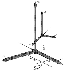
Yaw definition
Yaw is rotation around the Z-axis in relation to the previous frame. The previous frame is the starting coordinate system we are rotating. The figure illustrates a yaw rotation of 30°. Rotation about the Yaw angle yields new coordinate system (X1, Y1, Z1).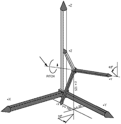
Pitch definition Pitch is rotation around the Y-axis in relation to the previous frame after yaw rotation has been applied. It means the rotation is made around newly obtained Y1 axis. The figure above illustrates a pitch rotation of 40°. Rotation about the Pitch angle yields new coordinate system (X2, Y2, Z2).
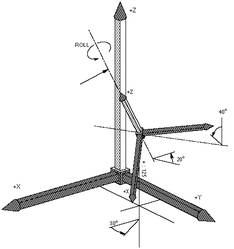
Roll Definition Roll is rotation around the Z-axis in relation to the previous frame, after the yaw and pitch rotations have been applied. It means the Roll rotation is around Z2 axis. The figure above illustrates a roll rotation of 20°. Rotation about the Roll angle yields new coordinate system (X3, Y3, Z3).


| NOTE | |
| Note that the order of the yaw, pitch and roll sequence is important! |
Homogenous Transformation Matrix:
This method of location representation is not used internally or in a user interface of the softMC but it is mostly used in the robotics literature. Therefore the representation is given in this document for demonstration and explanation purposes only. Location variable is represented as a (4 X 4) matrix:
loc = 
Where: xx_axis, yx_axis, zx_axis are normalized values defining the change of the x axis in relation to its initial position, etc ...
X, Y, Z are the position values of the tool center point relative to the robot base.
The last line (0 0 0 1) is used for normalization.
Example 1
if loc coordinates are {100, 80, 150, 45, 0, 0}
loc written as a transformation matrix will be :
loc = 
as there is only 45° of yaw rotation (rotation around Z axis) as it is illustrated.
The normal softMC system representation in programs is the {X,Y,Z, Yaw, Pitch, Roll} format. The homogenous matrix transformation is used here only for illustration purposes.
X Y Z Q (quaternions)
- 3 degrees of freedom in translation (X, Y, Z) expressed in mm, defining the position of the tool center point relative to the robot base.
- 3 degrees of freedom in rotation, expressed using the normalized quaternion Q described as a rotation around vector n for the angle phi:
[cos(phi/2), sin(phi/2)*n]
The quaternion rotation presentation is used internally by the system but is not directly available for the user. However in cases of user-kinematics, this must be taken into account. The quaternions are used only for illustration purposes, the softMC system uses Euler angles for all user inputs and outputs.
Joint coordinates
For joint coordinates, a location variable is defined by n components representing the values in degrees (or mm) of each axis (n-number degrees of freedom according to the zero position of the kinematics model.
A location in joint coordinates is an array of n joint values:
Jnt_loc = {jnt1, jnt2, jnt3, jnt4, jnt5, jnt6}
Individual coordinates can be accessed via index definition in the form {i}: Jnt_loc{1}, Jnt_loc{2}, …
The above definition allows us to perform computation on locations in joint coordinates, for instance addition, subtraction, etc ...
Cartesian coordinates
For cartesian coordinates, a location variable is defined by 6 components representing the values:X, Y, Z, Yaw, Pitch, Roll.
Cartesian system variables: here, setpoint
loc = <robot>.here system maintained variable which returns the current transformation of the tool tip referred to the WORLD reference frame of the arm. Cartesian location definition: The curly brackets preceded by the "#" sign are used by the system to differentiate between joint and location positions. #{x_value, y_value, z_value, yaw_value, pitch_value, roll_value }
Example 1
If "r" is the radius of a circle and "angle" is the angle of rotation about the circle, then the transformation :
#{r*COS(''angle''),'' r''*SIN(''angle''), 0, 0, 0, 0 } will yield points on that circle.
Point Manipulations
Compound operator
A compound operator between two cartesian points is defined. The compound operator is defined using the ':' sign.
Thus, a compound transformation is written:
location = loc1 : loc2
which means that loc2 is defined in relation to loc1.
A compound transformation is the result of the multiplication of the corresponding homogeneous transformation matrix by another homogeneous transformation matrix:

Or using quaternions:
![{\displaystyle [(X,Y,Z)+Rot_{Q}1(X',Y',Z');Q_{1}\cdot Q_{2}]=[X,Y,Z,Q_{1}]:[X',Y',Z',Q_{2}]}](https://en.wikipedia.org/api/rest_v1/media/math/render/svg/6f1d52a8489be6b54fc6706b86e4440565c175d0)
Example
point_name3 = point_name1:point_name2
point_name3 is the compound transformation of point_name1 and point_name2 and is defined in the basic frame (WORLD).

Note that the sequence of a compound transformation has to be respected (operator is not commutative).
Example
hop = #{20,130,45,30,0,90 }:point_name does not define the same transformation as: hop = point_name: #{20,130,45,30,0,90 }
Inverse of a location
Inverse transformations are of prime importance in robotics when manipulating trajectories in space. This notion is mainly used in relation to frames to move a trajectory into another place without re-teaching the points. The function which defines the inverse is called INVERSE.
The inverse of a transformation is the computation of the inverse of the transformation matrix.
INVERSE(loc) = 

Or using quaternions:
INVERSE(loc) = 
Example: benefit of inverse transformations
Example 2
If "frame" is a transformation defining the position of the center of the circle and the plane in which it lies, the following program segment will move the robot toll point around the circle in steps of 1 degree.
FOR angle = 0 TO 360
MOVE frame:#{r *COS( angle *pi/180), r *SIN( angle *pi/180), 0, 0, 0, 0}
END
MOVE #{10,0,20,0,0,0):HERE:point = HERE is used as a location
Location assignments
loc =#{0,0,0,0,0,0}
A NULL transformation corresponds to the identity matrix.
NULL = 
Example
loc2 = loc1:loc
where loc is a NULL transformation
loc2 = 
- loc2 is equal toloc1
Inverse transformations and NULL transformations
Direct coordinate transformation
The direct coordinate transformation translates joint variables (in degrees) into location variables (in mm) of the tool point center (modal value), referenced to the robot base (modal value). The system function used in this case is: <location> = ToCart(<robot>, <joint position>) It converts a set of joint coordinates to an equivalent transformation value using the geometric data of the robot given as a function argument. The computed location represents the position and orientation of the end of the tool in the World coordinate system taking into consideration the current TOOL transformation and BASE offset. Application : trans = ToCart (jtloc) input : jtloc : joint
output: trans : computed location based on the given joint values of jtloc
See Also: TOCART
Example
The series of instructions below computes the position and orientation that the robot will be moved to if its current location is altered by rotating joint 1 by 10 degrees.
jtloc = pfb
jtloc {1} = jtloc {1} +10 trans = ToCart(jtloc)
Inverse coordinate transformation
The inverse coordinate transformation translates robot locations into joint positions according to configuration flags and the modal tool & base values.
The system function used in this case is: <joint position> = ToJoint(<robot>, <location>, <cfg. Flags>) See Also: TOJOINT {{Note | The conversion from cartesian into joint coordinates can result in several configuration solutions linked to a cartesian position. The desired configuration can be forced by altering configuration flags. } The number and type of configuration flags depends on each robot type. The following table defines configuration flags of each supported robot type:
| Robot type | Flag | Values | Bit No. (ToJoint) | |
| 1 | 2 | |||
| PUMA | Arm | lefty | righty | 0 |
| Elbow | below | above | 1 | |
| Wrist | noflip | flip | 2 | |
| SCARA | Arm | lefty | righty | 0 |
| DELTA | - | - | - | |
The configuration flag argument of the tojoint function is defined as:

Note! Constants lefty, righty, above, below, flip and noflip are defined as built-in constants of the MC-Basic language.
Example
In PUMA RX90 manipulator the following joint point: {0 , -45 , 135 , 0 , 90 , 0} corresponds to the Cartesian coordinates:
#{768.198 , 0 , 233.198 , 0 , 180 , 0}
and the following configuration: lefty, above, noflip. Therefore the configuration flags of the ToJoint function will be expressed as: (1-0)*20 + (2-1)*21 + (1-1)*22 = 2. So the opposite direction will be:
-->?ToJoint(#{768.198 , 0 , 233.198 , 0 , 180 , 0},0b010)
{0 , -45 , 135 , 0 , 90 , 0}
-->
Trajectory Interpolation
Joint interpolated (natural) motion MOVE
The MOVE instruction causes a joint-interpolated motion. That is, intermediate command points between the initial and final robot locations are computed by interpolating linearly between the initial and final joint positions. Any changes in configuration requested by the program are executed during the motion. If the MOVE is given on joint coordinates then the command configuration (acmd, ecmd, wcmd) flags must agree (be the same or “auto”) with the configuration flags of the given target point. Joint interpolated movement is determined by the regular MC group parameters (vcruise, acc, dec, jerk).
Linear interpolated motion MOVES
The MOVES instruction causes a straight-line motion. During such a motion, the tool center point is moved along a straight-line path and is smoothly rotated to its final orientation. Changes of configuration are not allowed during straight-line motions, except in cases when the commanded configuration flags are given with “auto” value and the movement allows it. Straight-line movement is determined by the pairs of translation/rotation parameters for velocity, acceleration and jerk: (vtran, atran, dtran, vrot, arot, jrot).
Circular (arc) interpolated motion MOVES
The CIRCLE instruction causes a circular or arc motion. During such a motion, the tool center point is moved along a arc (or circle) path and is smoothly rotated to its final orientation. Changes of configuration are not allowed during circular-line motions, except in cases when the commanded configuration flags are given with “auto” value and the movement allows it. Note that in cases of circular interpolation tool orientation is rotated around vector normal on the circle plane from its initial to its final value. Circular movement is determined by the pairs of translation/rotation parameters for velocity, acceleration and jerk: (vtran, atran, dtran, vrot, arot, jrot).
ORIENTATION INTERPOLATION DESCRIPTION
Having the initial and final orientation expressed as quaternions (Qi, Qf) the orientation interpolation will be done according to the formula:
![{\displaystyle Q(t)=[cos(\phi (t)/2),sin(\phi (t)/2)\cdot n]Q_{i}}](https://en.wikipedia.org/api/rest_v1/media/math/render/svg/3614cad0c428149e0421675bd35015e1c0ee7951)
Where vector r and angle are defined from:

![{\displaystyle [cos(\phi (t)/2),sin(\phi (t)/2)\cdot r]=Q_{f}\cdot Q_{i}^{-1}}](https://en.wikipedia.org/api/rest_v1/media/math/render/svg/202eeb84c24435bc733dcf57d625d536c6aa42ed)
The rate of change of angle is proportional to the rate of change of the WORLD position (X,Y,Z) of the robot movement.
The angle phi of the above formula can be always changed in two directions: positive & negative. One will be shorter the other longer, but this does not necessary give shorter movements in joint space. Therefore the user has the ability to influence orientation interpolation using the OrientationFollowing property of the robot. The values of the orientation-following property are:
0 – Shortest path in world coordinates ( shortest orientation path)
1 – Shortest path in joint coordinates (shortest movement of fourth joint for SCARA).
2 - longer path in world space
3 - longer path in joint space
4 – Positive direction in world space
5 – Positive direction in joint space - sign of last joint
6 – Negative direction in world space
7 – Negative direction in joint space - sign of last joint
See Also:
GENERAL REMARKS ABOUT MOVEMENTS
There are four different combinations of interpolation type and target points. The target point can be given in world or in joint coordinates and the interpolation can be straight-line or joint-interpolated (natural). For both cases of straight-line (cartesian interpolation) motion the following rules apply:
- The actual value of Arm - flag (afbk) does not change during the motion. It’s initial and final value must be the same, except the case when the motion starts form an “auto” value of the flag.
- The actual value of Elbow - flag (efbk) does not change during the motion. It’s initial and final value must be the same, except the case when the motion starts form an “auto” value of the flag.
- The actual value of Wrist –flag (wfbk) does not change during the motion it’s initial and final value must be the same, except two cases: when the motion starts form an “auto” value of the flag. when the wcmd is given with an “auto” value and the motion passes through wrist singularity (pcmd{5} =0) not affecting the fourth and the sixth joint.
Straight line motion with joint target (MOVES {…,…,…})movement is interpolated in Cartesian space so the changes of XYZ coordinates are linear. User can specify configuration command flags (acmd, ecmd, wcmd) but they must comply with the given target point. If from some reason (usually it is the orientation-following ) the given target point is not reached in joint space (in world space it is always reached!) an error will be generated. Typically the last three joints are reached in other values which differ for ±360 degrees, but the Cartesian point is the same.
In this case the OrientationFollwing flag is ignored and all computation will be done as the user set the value of 1 (closest path in joint space).
Straight line motion with Cartesian target (MOVES #{…,…,…})movement is interpolated in Cartesian space so the changes of XYZ coordinates are linear. User can specify configuration command flags (acmd, ecmd, wcmd), only the proper setup will be allowed, else an error will be returned.
Joint –interpolated motion with joint target (MOVE {…,…,…})movement is interpolated in Cartesian space so the changes of j1,…,j6 are linear. The configuration flags are ignored.
Joint –interpolated motion with Cartesian target (MOVE #{…,…,…})movement is interpolated in Cartesian space so the changes of j1,…,j6 are linear. The configuration flags are taken into account when computing target coordinates. If “auto” configuration flag is selected the point closest to the target will be chosen.
Case of invalid selection of configuration flags.
Normally the system does not allow configuration flag change during cartesian-interpolated motions (MOVES, CIRCLE, PASSTHROUGH) if such a change is commanded an error will be returned and the motion will be not started. This occurs when the command configuration flags (acmd, ecmd, wcmd) differs from the feedback configuration flags at the start point (afbk,efbk,wfbk). However exceptions exist when the command flags are given with “auto(0)” value, depending on the specific robot model, the system chooses the same configuration as in the start position.
In PUMA kinematics, there are special cases when the configuration flags can change during the cartesian-interpolated motion.
A change of the WRIST flag can be obtained when the wcmd is set to “auto(0)” and issuing one of the straight line motions. If such a motion passes thorough zero of the fifth joint angle there is a possibility that the wrist flag is changed. However, this can sometimes introduce opposite rotations of joints 4 and 6. If this rotation is too fast an error message will be returned and the motion will be canceled. In order to prevent it user can command low Cartesian speed (vrot, vtran) near these points.
A change of the ARM and ELBOW flags can be obtained in the case of straight-line motion (MOVES) going through the arm point singularity which in case of PUMA robot with d2=0 is point X = 0, Y = 0, Z =a2+d4+d6 , or in case d2≠0 (RX60) is a circle X = d2 cos α, Y = d2 sin α, Z = a2+d4+d6.

Movements with the target point given in joint coordinates are treated differently. In these cases target joint coordinates and command configuration flags must comply (be the same or have auto value). If this is not the case motion will be not executed and an error will be returned.
User Frame system
The softMC system is enriched with a set of user-definable working frames. All working frames are available both modally and nodally. All user frames must have the same location type (XYZ, XYZR, XYZYPR …) as the parent robot.
Working with robots the following user-definable frames are provided:
- World frame.Default Cartesian coordinate system. This frame is usually located at the robot base.
- Base frame.The frame of the robot from the user-point of view. Normally used to correct rotation or inclination of robot mounting. (Usable for ceiling mounted robots).
- Tool frame.Frame attached to the tool mounted on the robot, closely related to the tool geometry. Useful for describing tasks made by the attached tool (grinding, debarring, screwing, …)
- Machine-Table Frame.Frame related to the machine robot is working with.
- Work-Piece Frame.Frame related to the work-piece mounted on the machine robot is working with.

All location properties of the robot are always expressed using the whole user-frame system, therefore always in the Work-Piece Frame defined by the whole user-frame chain. Using the previously defined compound transformation we have:
| NOTE | |
| Setting new values the tool property can cause a significant increase of position error (pe). The value of pe is always calculated at the tool-tip point, so increased tool length and small orientation errors can lead to an increased pe. This is obvious when putting pe into above equation: |
TOOL
Tool is a Robot property which informs the system to use the specified location as the tool transformation. It defines the position and orientation of the tool tip in relation to the center of the tool flange. The default tool transformation is the NULL transformation, which can be expressed as TOOL = #{0,0,0,0,0,0}
Example
Puma.tool = #{25,0,100,0,45,0}
BASE
Base is a Robot property which informs the system to use the specified location as the base transformation. It defines the position and orientation of the arm in the cell according to the WORLD reference.
The default base transformation is the NULL transformation, which can be expressed as Puma.base = #{0,0,0,0,0,0}
MachineTable
MachineTable is a Robot property which informs the system to use the specified location as the machinetable transformation. It defines the position and orientation machine working frame relative to the BASE reference.
The default machinetable transformation is the NULL transformation, which can be expressed as Puma.MachineTable = #{0,0,0,0,0,0}
WorkPiece
WorkPiece is a Robot property which informs the system to use the specified location as the workpiece transformation. It defines the position and orientation of work-piece relative to the MACHINE TABLE reference.
The default base transformation is the NULL transformation, which can be expressed as Puma.WorkPiece = #{0,0,0,0,0,0}


So we have:
Pbase =Base:P world:Tool Pbase =MachineTable:WorkPiece:P WorkP For the given setup user frames will be: Base = #{300,200,1000,0,180,180} Tool = #{50,0,0,90,45,0} MachineTable = #{400,100,0,0,0,0} WorkPiece = #{20,70,150,0,90,-90}
Therefore we have:
PWP = WorkPiece -1: MachineTable-1:Base:PWorld:Tool
Side effects
Setting the any of the user frames modally (tool, base, machinetable, workpiece), have an immediate effect on all the position computations:
- Setpoint
- Here
- Start
- Dest
- ToJoint
but doesn’t affect the current motion.