Difference between revisions of "Galileo Sphere Robot (GSR) Kinematics/zh-hans"
(Created page with "{{Languages}} =Robot Kinematics for Galileo Sphere Robot= Image:GSR-SETUP.JPG 400px 400px ==Robot Defi...") |
|||
| Line 1: | Line 1: | ||
| − | {{Languages}} | + | {{Languages|Galileo_Sphere_Robot_(GSR)_Kinematics}} |
| − | = | + | =伽利略球机器人的机器人运动学= |
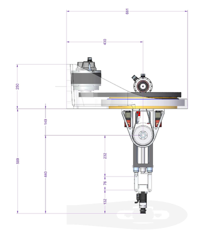
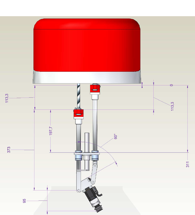
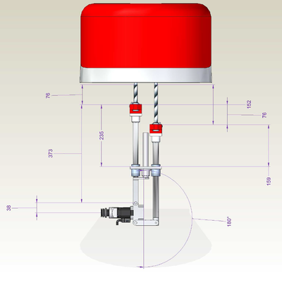
[[Image:GSR-SETUP.JPG]] [[Image:GSR-SIDE-DRAWINGS.PNG|400px]] [[Image:GSR-FRONT-DRAWING.PNG|400px]] | [[Image:GSR-SETUP.JPG]] [[Image:GSR-SIDE-DRAWINGS.PNG|400px]] [[Image:GSR-FRONT-DRAWING.PNG|400px]] | ||
| − | == | + | ==机器人定义为具有预定义点类型的一组轴== |
| − | + | 机器人运动学将被分配到具有'''XYZPR'''(x,y,z,pitch,roll)点类型的新模型类型('''15''')。 以下行将GALILEO机器人定义为新的系统变量: | |
<pre> | <pre> | ||
Common Shared GALILEO As Group Axnm = A1 Axnm = A2 Axnm = A3 Axnm = A4 Axnm = A5 model = 15 of '''xyzpr''' | Common Shared GALILEO As Group Axnm = A1 Axnm = A2 Axnm = A3 Axnm = A4 Axnm = A5 model = 15 of '''xyzpr''' | ||
</pre> | </pre> | ||
| − | == | + | ==机器人运动学 == |
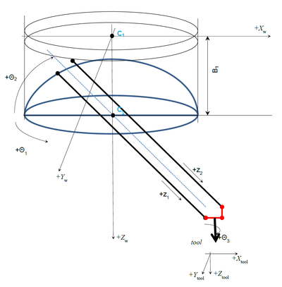
[[Image:GSR0.PNG|400px]] | [[Image:GSR0.PNG|400px]] | ||
| − | === | + | ===关节坐标系=== |
{| border = 1 | {| border = 1 | ||
| Line 32: | Line 32: | ||
|} | |} | ||
| − | ''' | + | '''三个旋转轴:''' |
| − | * theta1 – | + | * theta1 – 大水平旋转 (J1 或 joint #1) |
| − | * theta2 – | + | * theta2 – 俯仰轴(J2 或 joint #2) |
| − | * theta3 – | + | * theta3 – 工具旋转 (J5 或 joint #5) |
| − | ''' | + | '''两个线性轴:''' |
| − | * Z1 (J3 | + | * Z1 (J3 或 joint #3) |
| − | * Z2 (J4 | + | * Z2 (J4 或 joint #4) |
| − | + | Z1是无连杆的线性轴。 | |
| − | + | MC-Basic语言中机器人关节点的一般介绍是(大括号内的数值表达式): | |
| − | |||
<pre>{J1, J2, J3, J4, J5}</pre> | <pre>{J1, J2, J3, J4, J5}</pre> | ||
| − | === | + | ===笛卡尔坐标系=== |
| − | + | 机器人TCP(工具中心点)的笛卡尔坐标(世界)是(Xw,Yw,Zw)。 机器人工具Z轴的姿态总是表示为将Z世界(Zw)轴旋转到Z刀具(Zt)轴所需的旋转。 它可以用ZYZ旋转次数的3欧拉角(Yaw,Pitch,Roll)表示。 | |
'''Yaw Angle:''' | '''Yaw Angle:''' | ||
| − | + | 绕Zw轴旋转(Xw,Yw,Zw)到(X1,Y1,Z1) | |
'''Pitch Angle:''' | '''Pitch Angle:''' | ||
| − | + | 绕Y1轴旋转(X1,Y1,Z1)到(X2,Y2,Z2) | |
'''Roll Angle:''' | '''Roll Angle:''' | ||
| − | + | 绕轴Z2(X2,Y2,Z2)系统到(X3,Y3,Z3),与(XT,YT,ZT)重合 | |
| − | + | 由于给定的机器人只有5个自由度(DOF),所以我们只将姿态表示法减少到俯仰和翻滚角度。 这对应于绕Y2的旋转(旋转Yw与θ1之后获得的轴)和Z3工具Z轴(依次)。 | |
| − | + | 一般在MC-Basic语言中的介绍机器人笛卡尔点是(带哈希符号之前的大括号内的数值表达式列表): | |
<pre>#{X, Y, Z, Pitch, Roll}</pre> | <pre>#{X, Y, Z, Pitch, Roll}</pre> | ||
| − | = | + | =几何形状= |
| − | + | 机器人的重要几何参数是: | |
[[Image:GSR1.PNG|400px]] | [[Image:GSR1.PNG|400px]] | ||
| − | + | 参数列表: | |
{| border = 1 | {| border = 1 | ||
| − | | | + | |名称||单位||描述||MC-Basic 属性 |
|- | |- | ||
|D1||mm||Distance between the axes||<robot>.Link[1][1] | |D1||mm||Distance between the axes||<robot>.Link[1][1] | ||
|- | |- | ||
| − | |D2||mm|| | + | |D2||mm||工具安装杆||<robot>.Link[1][2] |
|- | |- | ||
| − | |D3||mm|| | + | |D3||mm||延长杆||<robot>.Link[1][3] |
|- | |- | ||
| − | |L1||mm|| | + | |L1||mm||工具长度||<robot>.Link[2][1] |
|- | |- | ||
| − | |B1||mm|| | + | |B1||mm||θ2旋转中心(C2)与θ1圆(C1)中心的垂直(Z)偏移。||<robot>.Link[2][2] |
|} | |} | ||
| − | + | 通过定义z轴(z1off和z2off)的零坐标,隐含定义了两个附加参数。两个z轴在同一行应为零(见图)。 这两个将包括从轴编码器零位置到θ2的旋转轴的偏移 - 包括连接到它的所有固定的附加联轴器(在图中未示出,因为它们不交替基本机器人运动学)。 | |
| − | |||
| − | {{Note/Important| | + | {{Note/Important|假设机器人具有对称的设置。 工具法兰在D2连杆的中间,theta2的旋转中心位于θ1圆的中间。 要达到这两项要求至关重要,否则运动学关系无效。 |
}} | }} | ||
| − | = | + | =奇异点= |
| − | + | 理论上说,这些运动学有两个奇点,我们称之为滚动奇异性和连杆奇异性(这些名称只是随意地给出,因为我们需要以某种方式表示它们),但是我们将只处理一个,而另一个对用户将不可用。以下为解释: | |
| − | == | + | ==旋转奇异点== |
[[Image:GSR-CONFIG.PNG|400px]] | [[Image:GSR-CONFIG.PNG|400px]] | ||
| − | + | 当θ<sub>1</sub>和θ<sub>3</sub>都是共线的时,发生这种奇异性。 它们的和(θ<sub>1</sub> + θ<sub>3</sub>)构建笛卡尔转角,并且这两个数字的任何组合将代表相同的转角。 | |
| + | |||
| − | == | + | ==连杆奇异== |
[[Image:GSR-RSING.PNG|400px]] | [[Image:GSR-RSING.PNG|400px]] | ||
| − | + | 这是一个典型的四杆机构奇异性,对于Z1X段的相同位置,Z2点有两个解决方案。 为了避免这种奇异点的问题,只能采取最小x角的解决方案(图中的x'角)。 | |
| − | = | + | =配置标志= |
| − | + | 实际上系统中应该有两个配置标志。 但是,由于其中的一个配置不允许,所以只有一个(ARM)用户可用(用于读取和写入)。 | |
[[Image:GSR-LSING.PNG|400px]] | [[Image:GSR-LSING.PNG|400px]] | ||
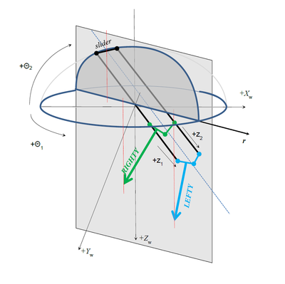
| − | + | Arm配置标志根据以下定义:<br> | |
| − | + | 如果工具尖端与θ<2>滑块位于同一侧,则为“RIGHTY”。 否则是“'LEFTY''' | |
| − | + | 或:<br> | |
| − | + | 如果 r > 0,Arm 为'''LEFTY'''<br> | |
| − | Arm is '''RIGHTY''' | + | 如果r<0,Arm is '''RIGHTY''' |
| + | 在MC-Basic语言中:<br> | ||
| − | + | * [[MC-Basic:robot.ARMCMD|<robot>.Acmd]]为命令配置 | |
| + | * [[MC-Basic:robot.ARMFBK|<robo>.Afbk]]当前(反馈)配置 | ||
| − | |||
| − | |||
| − | = | + | =典型的机器人姿态= |
| − | + | 以下列出了一些更好地了解工作空间坐标的典型姿势。 它们不需要代表机器人的可行位置(由于某些轴位置限制),但它们是完成和测试机器人运动学定义的好例子。 | |
[[Image:GSR-POS0.PNG|400px]] | [[Image:GSR-POS0.PNG|400px]] | ||
| − | • | + | • 水平位置,俯仰角= 90度: |
{0,0,Z1,Z2-D3,0} #{Z1+L1,B1,-90,0} | {0,0,Z1,Z2-D3,0} #{Z1+L1,B1,-90,0} | ||
| − | • | + | • 相同姿态旋转θ3 - 直接转换成旋转角度 |
{0,0,Z1,Z2-D3,45} #{Z1+L1,B1,-90,45} | {0,0,Z1,Z2-D3,45} #{Z1+L1,B1,-90,45} | ||
{0,0,Z1,Z2-D3,-45} #{Z1+L1,B1,-90,-45} | {0,0,Z1,Z2-D3,-45} #{Z1+L1,B1,-90,-45} | ||
| Line 145: | Line 144: | ||
| − | + | 水平位置,俯仰角= ±90度: | |
{90,0,Z1,Z1-D3,0} #{0,-(Z1+L1),B1,-90,0} | {90,0,Z1,Z1-D3,0} #{0,-(Z1+L1),B1,-90,0} | ||
{-90,0,Z1,Z1-D3,0} #{0,+(Z1+L1),B1,-90,0} | {-90,0,Z1,Z1-D3,0} #{0,+(Z1+L1),B1,-90,0} | ||
| Line 151: | Line 150: | ||
[[Image:GSR-POS2.PNG|400px]] | [[Image:GSR-POS2.PNG|400px]] | ||
| − | • | + | • 奇异点: |
{0,90,Z1,Z1-D3,0} #{0,0,B1+(Z1+L1),0,0} | {0,90,Z1,Z1-D3,0} #{0,0,B1+(Z1+L1),0,0} | ||
{R,90,Z1,Z1-D3,-R} #{0,0, B1+ (Z1+L1),0,0} for any R! | {R,90,Z1,Z1-D3,-R} #{0,0, B1+ (Z1+L1),0,0} for any R! | ||
| Line 247: | Line 246: | ||
| − | {{Note| | + | {{Note|在这一点上,我们有连杆奇异点}} |
Latest revision as of 08:15, 29 May 2017
| 语言: | English • 中文(简体) |
|---|
Contents
伽利略球机器人的机器人运动学
机器人定义为具有预定义点类型的一组轴
机器人运动学将被分配到具有XYZPR(x,y,z,pitch,roll)点类型的新模型类型(15)。 以下行将GALILEO机器人定义为新的系统变量:
Common Shared GALILEO As Group Axnm = A1 Axnm = A2 Axnm = A3 Axnm = A4 Axnm = A5 model = 15 of '''xyzpr'''
机器人运动学
关节坐标系
| Axis name | Joint | Type | Range | Units |
| Theta1 | J1 | Rotary axis | [-180,180] | deg |
| Theta2 | J2 | Rotary axis | [-10,90] | deg |
| Z1 | J3 | Linear | [Z1min,Z1max] | mm |
| Z2 | J4 | Linear | [Z2min,Z2max] | mm |
| Theta3 | J5 | Rotary axis | Multi turn | deg |
三个旋转轴:
- theta1 – 大水平旋转 (J1 或 joint #1)
- theta2 – 俯仰轴(J2 或 joint #2)
- theta3 – 工具旋转 (J5 或 joint #5)
两个线性轴:
- Z1 (J3 或 joint #3)
- Z2 (J4 或 joint #4)
Z1是无连杆的线性轴。
MC-Basic语言中机器人关节点的一般介绍是(大括号内的数值表达式):
{J1, J2, J3, J4, J5}
笛卡尔坐标系
机器人TCP(工具中心点)的笛卡尔坐标(世界)是(Xw,Yw,Zw)。 机器人工具Z轴的姿态总是表示为将Z世界(Zw)轴旋转到Z刀具(Zt)轴所需的旋转。 它可以用ZYZ旋转次数的3欧拉角(Yaw,Pitch,Roll)表示。 Yaw Angle: 绕Zw轴旋转(Xw,Yw,Zw)到(X1,Y1,Z1) Pitch Angle: 绕Y1轴旋转(X1,Y1,Z1)到(X2,Y2,Z2) Roll Angle: 绕轴Z2(X2,Y2,Z2)系统到(X3,Y3,Z3),与(XT,YT,ZT)重合
由于给定的机器人只有5个自由度(DOF),所以我们只将姿态表示法减少到俯仰和翻滚角度。 这对应于绕Y2的旋转(旋转Yw与θ1之后获得的轴)和Z3工具Z轴(依次)。
一般在MC-Basic语言中的介绍机器人笛卡尔点是(带哈希符号之前的大括号内的数值表达式列表):
#{X, Y, Z, Pitch, Roll}
几何形状
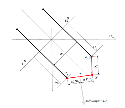
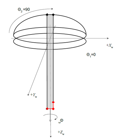
机器人的重要几何参数是:
参数列表:
| 名称 | 单位 | 描述 | MC-Basic 属性 |
| D1 | mm | Distance between the axes | <robot>.Link[1][1] |
| D2 | mm | 工具安装杆 | <robot>.Link[1][2] |
| D3 | mm | 延长杆 | <robot>.Link[1][3] |
| L1 | mm | 工具长度 | <robot>.Link[2][1] |
| B1 | mm | θ2旋转中心(C2)与θ1圆(C1)中心的垂直(Z)偏移。 | <robot>.Link[2][2] |
通过定义z轴(z1off和z2off)的零坐标,隐含定义了两个附加参数。两个z轴在同一行应为零(见图)。 这两个将包括从轴编码器零位置到θ2的旋转轴的偏移 - 包括连接到它的所有固定的附加联轴器(在图中未示出,因为它们不交替基本机器人运动学)。
| IMPORTANT | |
| 假设机器人具有对称的设置。 工具法兰在D2连杆的中间,theta2的旋转中心位于θ1圆的中间。 要达到这两项要求至关重要,否则运动学关系无效。 |
奇异点
理论上说,这些运动学有两个奇点,我们称之为滚动奇异性和连杆奇异性(这些名称只是随意地给出,因为我们需要以某种方式表示它们),但是我们将只处理一个,而另一个对用户将不可用。以下为解释:
旋转奇异点
当θ1和θ3都是共线的时,发生这种奇异性。 它们的和(θ1 + θ3)构建笛卡尔转角,并且这两个数字的任何组合将代表相同的转角。
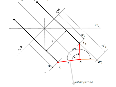
连杆奇异
这是一个典型的四杆机构奇异性,对于Z1X段的相同位置,Z2点有两个解决方案。 为了避免这种奇异点的问题,只能采取最小x角的解决方案(图中的x'角)。
配置标志
实际上系统中应该有两个配置标志。 但是,由于其中的一个配置不允许,所以只有一个(ARM)用户可用(用于读取和写入)。
Arm配置标志根据以下定义:
如果工具尖端与θ<2>滑块位于同一侧,则为“RIGHTY”。 否则是“'LEFTY
或:
如果 r > 0,Arm 为LEFTY
如果r<0,Arm is RIGHTY
在MC-Basic语言中:
- <robot>.Acmd为命令配置
- <robo>.Afbk当前(反馈)配置
典型的机器人姿态
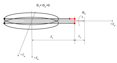
以下列出了一些更好地了解工作空间坐标的典型姿势。 它们不需要代表机器人的可行位置(由于某些轴位置限制),但它们是完成和测试机器人运动学定义的好例子。
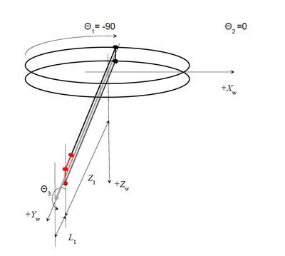
• 水平位置,俯仰角= 90度: {0,0,Z1,Z2-D3,0} #{Z1+L1,B1,-90,0}
• 相同姿态旋转θ3 - 直接转换成旋转角度 {0,0,Z1,Z2-D3,45} #{Z1+L1,B1,-90,45} {0,0,Z1,Z2-D3,-45} #{Z1+L1,B1,-90,-45}
水平位置,俯仰角= ±90度:
{90,0,Z1,Z1-D3,0} #{0,-(Z1+L1),B1,-90,0}
{-90,0,Z1,Z1-D3,0} #{0,+(Z1+L1),B1,-90,0}
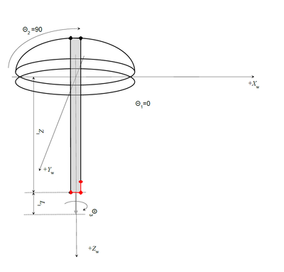
• 奇异点: {0,90,Z1,Z1-D3,0} #{0,0,B1+(Z1+L1),0,0} {R,90,Z1,Z1-D3,-R} #{0,0, B1+ (Z1+L1),0,0} for any R!
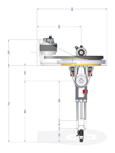
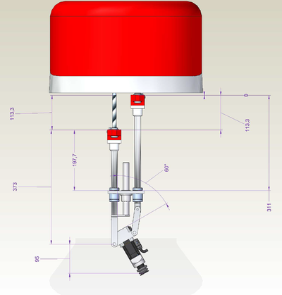
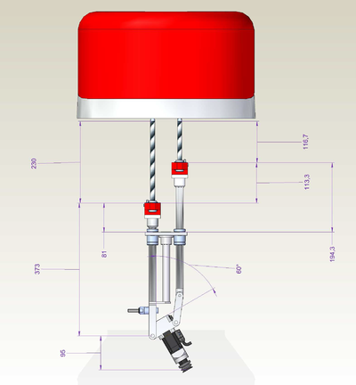
GSR light v2 sezione T2 Z out
-->move {0,90,386+76,386,0}
-->?setpoint
#{-7.41629e-14 , 0 , 743 , 0 , 0}
-->
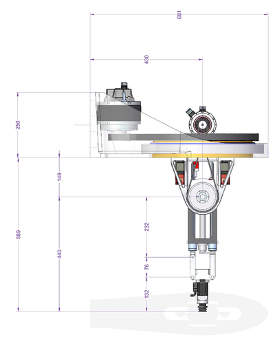
GSR light v2 sezione T2 Z in
-->move {0,90,232+76,232,0}
-->?setpoint
#{-2.26485e-14 , 0 , 589 , 0 , 0}
-->
GSR light v02 Z.in T3.60
-->moves {0,90,113.3+373,373,0}
-->?setpoint
#{60.8857 , 0 , 730.64 , -29.986 , 0}
-->?113.3+373+95+149
730.3
GSR light v02 Z.out T3.60
-->moves {0,90,230+373,230+373-113.3,0}
-->?setpoint
#{60.8857 , 0 , 847.34 , -29.986 , 0}
-->?230+373+95+149
847
-->
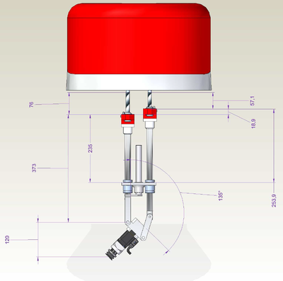
GSR light v02 Z.in T3.135
-->move {0,90,76+373,76+373 - 18.9,0}
-->?setpoint
#{-104.514 , 0 , 718.183 , 45.022 , 0}
-->?120+373+76+149
718
-->
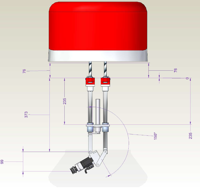
GSR light v02 Z.in T3.150
-->move {0,90,76+373,76+373,0}
-->?setpoint
#{-133.315 , 0 , 696.909 , 60 , 0}
-->?99+373+76+149
697
GSR light v02 Z.in T3.180
-->move {0,90,76+373,76+373+76,0}
-->?setpoint
#{-170 , 0 , 636 , 90 , 0}
-->?38+373+76+149
636
-->
| NOTE | |
| 在这一点上,我们有连杆奇异点 |
