Programmable Limit Switch
| Language: | [[::Programmable Limit Switch|English]] |
|---|
Contents
- 1 PLS Overview
- 2 PLS Functional Description
- 3 PLS Commands and Properties
- 4 Axis-PLS Programming Sequence
- 5 PLS Source
- 6 PLS High Accuracy
PLS Overview
A programmable limit switch (PLS) monitors position feedback on both real and simulated axes. When the axis reaches any of the defined PLS positions,
the PLS toggles the state of a specified system output, either digital or simulated.
A PLS offers more flexibility than a limit switch, as it allows many trip points and can be reconfigured on-the-fly.
PLS positions are defined in an array and must have values that are monotonic increasing.
Any number of positions can be defined for a PLS.
Any number of PLS switches can be defined for an element (axis or group). However, the number of defined PLS switches will have a direct affect on system performance.
The PLS is scanned at a rate of once per motion bus cycle.
Implementation of PLS in the Product includes three types of functionalty:
- Axis-PLS: PLS positions defined for an axis
- Path-PLS: PLS positions defined according to a motion path
- High accuracy PLS: PLS positions are extrapolated and set based on system position, speed and acceleration. For use in high speed applications.
PLS Functional Description
Output State
A PLS toggles an output when a specified position is reached. The state is toggled each time the position is reached,
irrespective of the direction of motor travel.
PLS Polarity
The property PLSPolarity allows you to control the initial polarity of the PLS output, which is specified as 1 or 0. The default value is 0.
The output state is set when the PLS is enabled (PLSEnable).
The state of the output is determined by the axis position at the moment of PLSEnable, according to the following scheme:
If PCMD < PLSPosition[1]
- Output = negative PLSPolarity (=1)
If PCMD >= PLSPosition[1] and PCMD < PLSPosition[2]
- Output = PLSPolarity (=0)
If PCMD >= PLSPosition[2] and PCMD < PLSPosition[3]
- Output = negative PLSPolarity (=1)
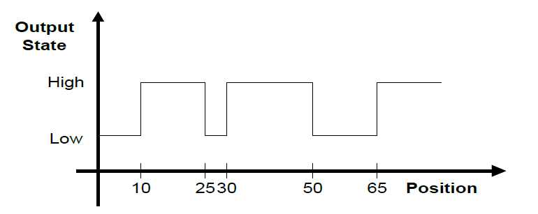
Consider the following example. The PLS positions are 10, 25, 30, 50 and 65. Polarity is 0. Once the PLS is enabled,
the output state will toggle on and off according to the location of the axis. Assuming PLS is enabled before position 10,
the output will toggle on at 10, remain on between 10 and 25, and toggle off between 25 and 30, and so on.
PLS Position Data
When a PLS is first defined, it does not have any associated positions. The CreatePLSData command is used to define the values for the PLS positions.
An unlimited number of PLS positions can be defined, but the array must be monotonic increasing.
PLS position values are always absolute (and not incremental). PLS positions are given in user units, and as such are affected by axis Displacement and PositionFactor properties.
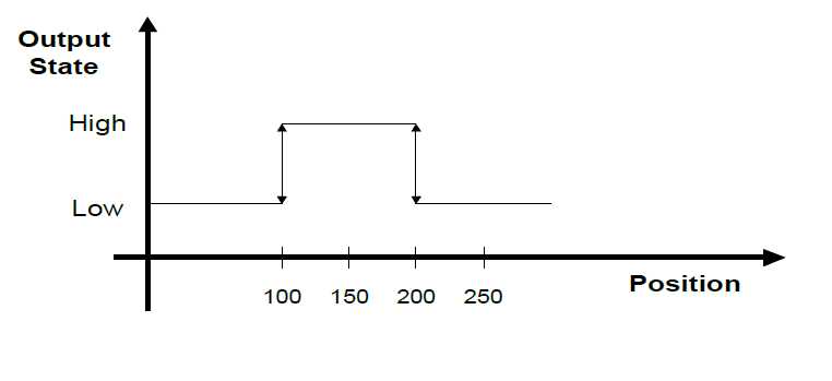
Consider the following example. Positions 100 and 200 are specified, and the initial state of the digital output after enabling is 0.
The following table shows how the state of output changes as the position changes.
| Position | Output State |
| 0 | 0 |
| 100 | 1 (Toggle) |
| 150 | 1 (No change) |
| 200 | 0 (Toggle) |
| 210 | 0 (No change yet) |
| 200 | 1 (Toggle again) |
| 150 | 1 (No change) |
| 100 | 0 (Toggle again) |
Hysteresis
If an axis stops at a specified PLS position, the state of the digital output may be continually toggled, due to slight oscillations in the actual axis position.
To accommodate this behavior, Product allows you to apply a hysteresis value around the output toggle positions.
Typically, 5 to 10 encoder counts (converted to position units) is sufficient.
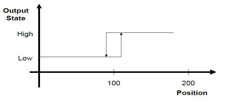
The output state is toggled when the PLS position is reached and surpassed by the hysteresis value.
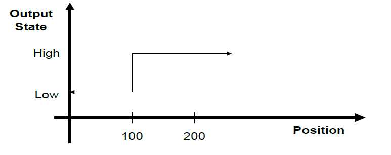
The following example shows a hysteresis value of 10; the output will toggle ON at position 110. It will toggle OFF at position 90.
If the axis driving the PLS stops at a PLS position within the hysterisis range, the PLS state does not change.
Hysteresis is necessary only if the system stops on or near a PLS position.
Repetition Interval
PLS positions may be repeated continually at a specified interval of encoder counts.
The repetition interval must be both positive and greater than the absolute value difference between the lowest and highest PLS position values. That is:
- Repetition Interval > abs(PLS_Pos_Max - PLS_Pos_Min)
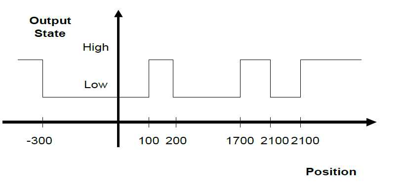
Consider the following example:
- PLS position values: -300, 100, 200
- Repetition Interval: 2000
- Polarity: 0
The output state is toggled at -300, 100, 200, and at 1700 (-300 + 2000), 2100 (100+2000), 2200, and at 3700 (-300 + 2000 + 2000), and so on in the position direction.
In the negative direction, the output state is toggled at -1800 (200 - 2000), -1900 (100 - 2000), -2300 (-300 - 2000), -3800, and so on.
Enable and Disable
When first defined, the PLS is disabled.
Once the PLS is enabled, the output is set according to the polarity and position, and the output pattern is generated.
The PLS must be disabled when modifying PLS properties.
PLS Commands and Properties
PLS Commands and Properties.
The following commands and properties are used for defining and using PLS functionality in a Product system.
| MC-Basic | Command/Property | Description |
| COMMON SHARED <PLS name> AS PLS <axis> <output> | Command | Declares a PLS variable. The name of the element and the output associated with the PLS are specified in the declaration. |
| CreatePlsData | Command | Creates a PLS data table containing the positions associated with a defined PLS. |
| DeletePls | Command | Deletes a defined PLS and all actions associated with that PLS. |
| PLSList | Command | Returns a list of the PLS names defined in the system. |
| WithPLS | Command | Nodal assignment of path-PLS. Enables path-PLS at the start of motion. The specified PLSes will be enabled during execution of the specified motion and disabled when the motion ends. |
| HWAssistance | Property | Enables/disables high-accuracy (hardware-enabled) PLS mode. |
| HWIOtime | Property | Returns the current contents of the hardware time buffers. Applicable only to high-accuracy PLS. |
| PLSAxisName/PLSElementName | Property | Returns the name of the axis or group for which the specified PLS is defined. |
| PLSDelayTime | Property | Returns the current contents of the PLS time buffers. |
| PLSEnable | Property | Enables or disables the PLS functionality. |
| PLSHysteresis | Property | Sets or queries the hysteresis level of a PLS. |
| PLSOutput | Property | Sets or queries the system output associated with a PLS. |
| PLSPolarity | Property | Sets or queries the initial polarity associated with a PLS. |
| PLSPosition | Property | Sets or queries an individual PLS position. |
| PLSPropagationDelay | Property | Expresses the elapsed time from the moment the position command is sent to the drive until it is set as a command value in the drive’s position loop. |
| PLSPropagationDisableDelay | Property | Propagation delay value, used when the PLS sets the external device to the disabled state. |
| PLSPropagationEnableDelay | Property | Propagation delay value, used when the PLS sets the external device to the enabled state. |
| PLSRelatedTo | Property | Flag used by PLSSource to define whether relative PLS position values are computed relative to the start of motion or the target position. |
| PLSRepeat | Property | Sets or queries the repetition interval of the PLS positions. |
| PLSSource | Propert | Defines certain attributes of PLS positions. |
Axis-PLS Programming Sequence
Step 1 – Declare
Create the PLS using COMMON SHARED ... AS PLS in 'Config.Prg' or in the terminal.
The declaration must define a name for the PLS, specify the element that drives the PLS, and specify the output controlled by the PLS.
The PLS is disabled until activated by PLSEnable=1.
The following example sets up 'MyPLS' as a PLS driven by axis A1 connected to system digital output 1.
Common Shared MyPLS as PLS A1 System.Dout.1
By default, the PLS has the following properties:
- One PLS position, set to 0.
- PLSPolarity = 0 (initial polarity of the PLS output off).
- PLSRepeat = 0 (no repetition)
- PLSHysteresis = 0 (no hysteresis)
See: Input/Output.
Step 2 – Positions
Create the PLS data structure and define the PLS position data using CreatePlsData.
The position array is 1- based, and position values must be monotonic increasing.
An attempt to access an index outside the array will produce an error.
For example:
CreatePLSData 4 MyPLS
MyPLS.PLSPosition[1] = 1000
MyPLS.PLSPosition[2] = 1100
Alternately, use the short form PPOS instead of PLSPosition:
MyPLS.Ppos[3] = 2000
MyPLS.Ppos[4] = 2200
Step 3 – Initial Polarity
Set the initial polarity of the PLS output using PLSPolarity
.
PLSPolarity default is 0 (off), indicating the PLS output will toggle on at the first PLS position.
Change the initial polarity to 1 (on):
MyPLS.PLSPolarity = 1
PLSPOLARITY defaults to off, indicating the PLS state will be off after the first PLS position.
Step 4 – Repetition
To repeat the PLS function at recurring intervals, set the value of PLSRepeat to a non-zero, positive number.
For example, repeat the PLS at every 10,000 position units:
MyPLS.PLSRepeat = 10000
Step 5 – Hysterisis
Set PLSHysteresis if the application requires it. Otherwise, leave it set to 0. The value is in user units.
MyPLS.PLSHysteresis = 0.01
Step 6 – Enable
Enable the PLS:
MyPLS.PLSEnable = 1
Additional PLS Programming Instructions
PLS State
The PLS must be disabled in order to modify various PLS properties, modify PLS position values, and delete a PLS.
Disabling a PLS also helps conserve CPU resources.
Disable a PLS:
MyPLS.PLSEnable = 0
Enable a PLS:
MyPLS.PLSEnable = 1
Query the state of a PLS:
?MyPls.PLSEnable
if(MyPLS.PLSEnable = 0)
Drive an event via PLSEnable:
EventOn MyEvent MyPLS.PLSOutput = 1
Delete a PLS
A PLS can be removed from the system only when the PLS is disabled and there are no tasks in memory.
Delete a PLS:
DeletePLS MyPLS
Query the PLS Axis Name
Query the name of the axis that activates the PLS:
?MyPLS.PLSAxisName
MyPLS.PLSAxisName = AXIS1
Query the PLS Output State
Query the state of the PLS output by querying the digital output associated with the PLS.
For example, if PLS output is assigned to SYSTEM.DOUT.1, query the state of SYSTEM.DOUT.1:
?Sys.Dout.1
Sys.Dout.1 = 0
Axis-PLS Program Example – PLS Setup
The following program example demonstrates the set up of a PLS data structure.
- NOTE: The PLS data object must first be defined in Config.prg or Terminal:
- Common Shared <PLS Name> as PLS <Axis> System.Dout.<DOut number>
PLS SETUP PROCEDURE PROGRAM EXAMPLE
PLS Source
PLSSource defines the type of position that toggles the PLS output.
The following table shows how PLSSource defines the PLS position for axis-PLS and path PLS.
PLSSource can be based either on an absolute position (either XYZ or axis), or on a position relative to the current movement. The difference is evident only during motion blending (and not more than 2 motions).
When PLSSource is relative, and actual blending occurs (the time during which two motions are executed simultaneously), the system executes two separate PLS events.
| Source | Description | Absolute/Relative | Axis PLS | Path PLS |
| PositionCommand | Axis position command | Absolute | Yes | – |
| PositionFeedback | Axis position feedback | Absolute | Yes | - |
| PositionExternal | External position | Absolute | Yes | – |
| Setpoint1 | X axis position (Setpoint{1} value) | Absolute | – | Yes |
| Setpoint2 | Y axis position (Setpoint{2} value) | Absolute | – | Yes |
| Setpoint3 | Z axis position (Setpoint{3} value) | Absolute | – | Yes |
| PathLength | Distance on the path, in user units | Relative to start/ target position | Yes | Yes |
| PathPercentage | Percentage of the path | Relative to start/ target position | Yes | Yes |
| PathTime | Time duration, in milliseconds | Relative to start/ target position | Yes | Yes |
Path Percentage and Path Length
PathPercentage and PathLength are are discontinuous variables that change their value abruptly at the transition point between two consecutive movements.
PathPercentage is a percentage of the motion path from the start position. It has no physical attribute. This variable is universal, as it can be used for all types of motions.
It can be very useful in motions having a dominant orientation.
Example: At point A, the source value changes from 100 to 0.
- MOVE A PLSSource 0 → 100
- MOVE B PLSSource 0 → 100
For PathPercentage, the values of PLSPosition, PLSHysteresis and PLSRepetition are percentages on a scale of 0 to 100. Negative values are considered 0; values greater than 100 are considered 100.
PathLength is the distance of the position from the start position, in position user units, such as millimeters.
Example: At point A, the source value changes from L1 to 0.
- MOVE A PLSSource 0 → L1
- MOVE B PLSSource 0 → L2
In a straight line motion (MOVES), PathLength is the distance from the start position.
In a joint interpolated motion (MOVE), PathLength has no physical attribute.
In circular interpolation, you can set PathLength as either the arc length or the angle from the start position.
If units are not homogenous, the value in aggregate units is used for PathLength. For circular interpolation this will be the angle on the circle-arc from the start position.
Path Time
Path time is the time elapsed from the start of the motion.
Path time is applicable only in time-based profiles (PRFTYPE = 2).
Setpoints
Setpoints are XYZ coordinates. This is the easiest method of defining a PLSsource, as it can be applied to any type of motion interpolation.
However, it may cause multiple triggering of the PLSPosition during one movement.
Setpoint sources are defined in the robot world frame.
During Conveyor Tracking, Setpoint1, Setpoint2, Setpoint3 assume the values of absolute robot coordinates (Setpoint, Here) and not robot frame coordinates moving with the robot.
During joint-interpolated motions (MOVE), values of Setpoint1, Setpoint2, Setpoint3 are interpolated linearly between the samples. Therefore, depending on the sample rate and velocity, an interpolation error may occur.
PLS Execution during PROCEED Command
The STOP command disables all PLS events in the currently executing motion.
The PROCEED command is used to resume execution of a motion that was stopped by a STOP command issued by a task other than the one moving the axis or group.
Depending on PLSsource, the PROCEED command has the following effect on PLS events:
| PLSSource | If Absolute | If Relative |
| Axis-PLS/Absolute Modal: source defined according to the command PLSEnable. | PLS event will be executed. | Execution will begin at the first PLS position in the buffer. |
| Path-PLS/Absolute & Relative Nodal: source defined according to motion issued by the command WithPLS. | PLS event will be executed. | No execution because the original path no longer exists. |
PLS High Accuracy
PLS High Accuracy Overview
When PLS high accuracy is not active, the response time of the PLS switch is determined by the value of PositionErrorDelay.
When PositionErrorDelay = 3, for example:
- If PLSsource is a position command, the PLS output will be toggled 2 samples before the position command is set in the drive.
- If the PLSsource is position feedback, the PLS output will be toggled 1 sample after the event.
When PLS high accuracy is active, the response time of the PLS switch is determined by a combination of hardware and software functions.
In normal PLS functionality, the target position is compared to the actual position (either reference or feedback) at every system cycle, and a response occurs.
Since the system motion bus cycle is limited to 2 milliseconds, or even 4 milliseconds, the PLS response time may not be sufficient for high-speed applications such as laser cutting and packaging.
To overcome the scan time limitation, the PLS functionality includes a high-accuracy PLS timing mode (HWAssistance) in which the timing of the PLS is computed to an accuracy of microseconds.
When high-accuracy mode is active, the Product software extrapolates the exact time at which the axis will reach the PLS position, based on its current position, velocity and acceleration, and sets an output for that time.

