Difference between revisions of "AXY:PLS Software Specification/zh-hans"
| Line 30: | Line 30: | ||
== PLS极性 == | == PLS极性 == | ||
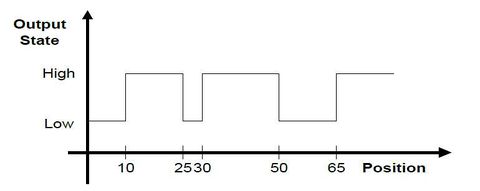
| − | + | 输出极性由PLS的极性决定。该属性确定PLS位置表的第一条目的输出极性,即在第一和第二条目之间的段中。如果轴的实际位置在别处,则相应地确定输出极性,因此当轴将到达第一段时,极性将如图所示。 | |
| − | + | 例如: 考虑以下PLS,其位置为10,25,30,50,65,极性为0,如图所示。 | |
[[File:AXY;PLS plolarity description.jpeg|Figure 1a: Programmable Limit Switch polarity description|480px]] | [[File:AXY;PLS plolarity description.jpeg|Figure 1a: Programmable Limit Switch polarity description|480px]] | ||
| − | + | 可以看出,第一段的极性(在10-25之间)如极性(1)所示。 在任何其他段中启用PLS将导致输出如图所示。 | |
| − | == | + | == 输出状态 == |
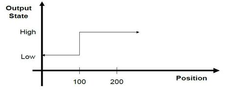
| − | + | 当达到指定的轴位置时,PLS会触发输出(数字或模拟)。输出的初始状态将由PLS极性属性决定。当达到位置时,输出的状态被触发。每当达到位置时也会切换状态,而不考虑电机的转动方向。 | |
[[File:AXY;PLS description.jpeg|Figure 1b: Programmable Limit Switch description|480px]] | [[File:AXY;PLS description.jpeg|Figure 1b: Programmable Limit Switch description|480px]] | ||
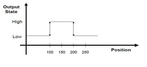
| − | + | 可以指定多个位置,在这种情况下,当达到每个位置时,数字输出的状态将被触发。例如,注意以下PLS规范:指定位置为100和200,启用后数字输出的初始状态为0.下表说明了输出状态如何随位置变化而变化。 | |
| − | |||
{|border="0" cellpadding="3" cellspacing="0" | {|border="0" cellpadding="3" cellspacing="0" | ||
| Line 51: | Line 50: | ||
|0||0 | |0||0 | ||
|- | |- | ||
| − | |100||1 ( | + | |100||1 (触发) |
|- | |- | ||
| − | |150||1 ( | + | |150||1 (没有变化) |
|- | |- | ||
| − | |200||0 ( | + | |200||0 (触发) |
|- | |- | ||
| − | |210||0 ( | + | |210||0 (还没有变化) |
|- | |- | ||
| − | |200||1 ( | + | |200||1 (再次触发) |
|- | |- | ||
| − | |150||1 ( | + | |150||1 (没有变化) |
|- | |- | ||
| − | |100||0 ( | + | |100||0 (再次触发) |
|- | |- | ||
|} | |} | ||
| Line 70: | Line 69: | ||
[[File:AXY;Multiple PLS positions.jpeg|Figure 2: Multiple PLS positions|480px]] | [[File:AXY;Multiple PLS positions.jpeg|Figure 2: Multiple PLS positions|480px]] | ||
| − | + | 如果轴位置围绕指定的PLS位置振荡,则每当指定位置被越过时,输出将被触发。 | |
| − | + | 初始输出状态由用户隐式指定。 当PLS启用时,输出设置为此状态。 | |
| − | == | + | == PLS位置数据 == |
| − | + | PLS位置数据存储在属于PLS机制的数据结构中。 使用CreatePlsData命令显式创建此数据结构。 | |
| − | + | PLS数据具有读/写访问权限。 用户必须确保PLS位置数据是单调的(以允许启用PLS)。 | |
| − | == | + | == 滞后 == |
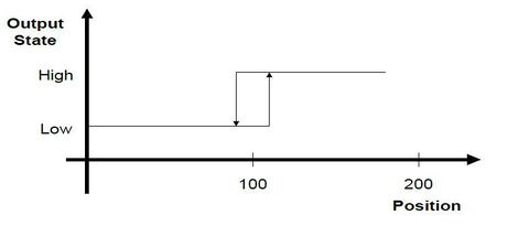
| − | + | 如果轴在指定的PLS位置停止,则由于实际轴位置的轻微不稳定性,数字输出的状态可能会持续触发。在这种情况下,可以选择指定滞后值。当并通过滞后值达到PLS位置时,输出状态将被触发。如在本示例中,如果滞后值为10,则输出将在位置110处从低电平变为高电平。当位置下降至90时,将返回到低电平。 | |
[[File:AXY;Hysteresis_in_PLS_position.jpeg|Figure 3: Hysteresis in PLS position|480px]] | [[File:AXY;Hysteresis_in_PLS_position.jpeg|Figure 3: Hysteresis in PLS position|480px]] | ||
| − | == | + | == 重复间隔 == |
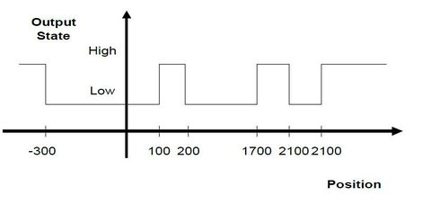
| − | + | 可以以指定的间隔持续重复PLS位置。因此如果PLS位置指定为100,例如,重复间隔为2000,则在正方向上,输出状态在100位置上触发,再次在2100,4100,等位置上触发。并且在负方向上,在 -1900, -3900等位置上触发。 | |
| − | + | 重复间隔必须为正,并且必须大于最小和最大PLS位置值之间的绝对值差. 即: | |
Repetition Interval > abs(PLS_Pos_Max - PLS_Pos_Min) | Repetition Interval > abs(PLS_Pos_Max - PLS_Pos_Min) | ||
| − | + | 示例: | |
* PLS Position values: -300, 100, 200 | * PLS Position values: -300, 100, 200 | ||
| Line 97: | Line 96: | ||
* Polarity: 0 | * Polarity: 0 | ||
| − | + | 输出状态在-300, 100, 200触发,同样在1700 (-300 + 2000), 2100 (100+2000), 2200, 和 3700 (-300 + 2000 + 2000) 等位置触发。 在负方向上输出状态在-1800 (200 - 2000), -1900 (100 - 2000), -2300 (-300 - 2000), -3800等位置触发。 | |
[[File:AXY;PLS Repetition Interval.jpeg|Figure 4: PLS Repetition Interval|480px]] | [[File:AXY;PLS Repetition Interval.jpeg|Figure 4: PLS Repetition Interval|480px]] | ||
| − | == PLS | + | == PLS 约束 == |
| − | * | + | * PLS的数量不受系统限制。 可以理解为定义的PLS数量与系统性能之间存在直接的权衡。 |
| − | * | + | * 每个PLS定义的PLS位置的数量不受限制。 |
| − | * | + | * 每个轴可以定义多个PLS。 |
| − | * | + | * PLSes以运动总线循环速率扫描 |
| − | == | + | == 启用和禁用 == |
| − | + | 定义后,禁用PLS(不生成输出模式)。 当PLS被使能时,输出被设置。 输出设置为定义的初始状态。只有当PLS被禁用时,才能更改PLS属性。每个启用的PLS都需要CPU资源。通过禁用未使用的PLS(s)来节省这些资源。 [[MC-Basic:pls.PLSENABLE|PLSEnable]] 控制PLS的状态。 | |
MyPLS.PlsEnable = ON | OFF | MyPLS.PlsEnable = ON | OFF | ||
| − | + | PLSENABLE查询PLS的状态: | |
?MyPls.PlsEnable | ?MyPls.PlsEnable | ||
if(MyPLS.PlsEnable = OFF) | if(MyPLS.PlsEnable = OFF) | ||
. . . | . . . | ||
| − | + | 或驱动事件: | |
EventOn MyEvent MyPLS.PlsOutput = ON | EventOn MyEvent MyPLS.PlsOutput = ON | ||
| − | ==PLS | + | ==PLS 输出状态== |
| − | + | 查询与PLS关联的数字输出,以查询PLS输出的状态。<br/> | |
| − | + | 例如,假设PLS输出被分配给SYSTEM.DOUT.1。 要确定PLS的输出状态,请查询SYSTEM.DOUT.1的状态: | |
| − | |||
| − | |||
-->?Sys.Dout.1 | -->?Sys.Dout.1 | ||
0 | 1 | 0 | 1 | ||
| − | == | + | ==示例== |
===Step 1=== | ===Step 1=== | ||
| − | + | 在Config.Prg或终端中使用[[MC-Basic:COMMON SHARED ... AS PLS|<nowiki>COMMON SHARED <PLS name> AS PLS</nowiki>]]声明PLS。您必须命名PLS,指定驱动PLS的轴,并命名要由PLS控制的输出。例如: | |
| − | |||
| − | |||
Common Shared MyPLS as PLS A1 System.Dout.1 | Common Shared MyPLS as PLS A1 System.Dout.1 | ||
| − | + | 将MyPLS设置为由连接到SYSTEM.DOUT.1的轴A1驱动的PLS。 | |
| − | + | 输出可以是数字输出(SYSTEM.DOUT.1到DOUT.20)或者可以是模拟输出之一(SYSTEM.VOUT.1到VOUT.32). | |
| − | + | 在Common Shared as PLS执行后, PLS禁用。 | |
| − | + | PLS的属性设置为: | |
| − | + | *单个PLS位置存在于0 | |
| − | * | + | *初始输出极性为1 |
| − | * | + | *PLSREPEAT设置为0. |
| − | * | + | *滞后设置为0.<br/> |
| − | * | + | 只要PLS保持禁用,可以明确设置这些属性。 |
| − | + | 您可以使用PLSOUTPUT来检查与给定PLS相关联的输出。 | |
| − | |||
| − | |||
===Step 2=== | ===Step 2=== | ||
Revision as of 10:02, 15 May 2017
| 语言: | English • 中文(简体) |
|---|
Contents
参考
介绍
可编程限位开关(PLS)是在达到指定轴位置时触发系统输出的机构。softMC中的PLS实现具有以下特点:
- 多位置规格
- PLS模式重复
- 位置滞后
- 启用和禁用PLS
- 输出可以是数字或模拟的
本文详细说明在softMC中PLS实现的功能。 描述功能并定义支持的命令。
定义
PLS – 可编程限位开关
PLS – 在PLS命令中指定的位置,其输出状态被切换。
Digital output – 可以映射到位于运动总线上的设备,驱动器输出中的任一个或 EtherCAT/CAN I/O模块。
(固件版本5.0及更高版本不支持本地; 它只支持传统的SERCOS II运动控制器。)
Soft output – 32个虚拟输出之一
PLS位置在数组中定义,允许您更改PLS位置的各个值。这个数组必须单调增加。 定义的位置数量和PLS数量没有限制。初始输出极性由Pls Polarity 指定。当PLS被使能时,输出状态被设置。
PLS功能描述
PLS极性
输出极性由PLS的极性决定。该属性确定PLS位置表的第一条目的输出极性,即在第一和第二条目之间的段中。如果轴的实际位置在别处,则相应地确定输出极性,因此当轴将到达第一段时,极性将如图所示。
例如: 考虑以下PLS,其位置为10,25,30,50,65,极性为0,如图所示。
可以看出,第一段的极性(在10-25之间)如极性(1)所示。 在任何其他段中启用PLS将导致输出如图所示。
输出状态
当达到指定的轴位置时,PLS会触发输出(数字或模拟)。输出的初始状态将由PLS极性属性决定。当达到位置时,输出的状态被触发。每当达到位置时也会切换状态,而不考虑电机的转动方向。
可以指定多个位置,在这种情况下,当达到每个位置时,数字输出的状态将被触发。例如,注意以下PLS规范:指定位置为100和200,启用后数字输出的初始状态为0.下表说明了输出状态如何随位置变化而变化。
| Position | Output State |
| 0 | 0 |
| 100 | 1 (触发) |
| 150 | 1 (没有变化) |
| 200 | 0 (触发) |
| 210 | 0 (还没有变化) |
| 200 | 1 (再次触发) |
| 150 | 1 (没有变化) |
| 100 | 0 (再次触发) |
如果轴位置围绕指定的PLS位置振荡,则每当指定位置被越过时,输出将被触发。
初始输出状态由用户隐式指定。 当PLS启用时,输出设置为此状态。
PLS位置数据
PLS位置数据存储在属于PLS机制的数据结构中。 使用CreatePlsData命令显式创建此数据结构。
PLS数据具有读/写访问权限。 用户必须确保PLS位置数据是单调的(以允许启用PLS)。
滞后
如果轴在指定的PLS位置停止,则由于实际轴位置的轻微不稳定性,数字输出的状态可能会持续触发。在这种情况下,可以选择指定滞后值。当并通过滞后值达到PLS位置时,输出状态将被触发。如在本示例中,如果滞后值为10,则输出将在位置110处从低电平变为高电平。当位置下降至90时,将返回到低电平。
重复间隔
可以以指定的间隔持续重复PLS位置。因此如果PLS位置指定为100,例如,重复间隔为2000,则在正方向上,输出状态在100位置上触发,再次在2100,4100,等位置上触发。并且在负方向上,在 -1900, -3900等位置上触发。
重复间隔必须为正,并且必须大于最小和最大PLS位置值之间的绝对值差. 即:
Repetition Interval > abs(PLS_Pos_Max - PLS_Pos_Min)
示例:
- PLS Position values: -300, 100, 200
- Repetition Interval: 2000
- Polarity: 0
输出状态在-300, 100, 200触发,同样在1700 (-300 + 2000), 2100 (100+2000), 2200, 和 3700 (-300 + 2000 + 2000) 等位置触发。 在负方向上输出状态在-1800 (200 - 2000), -1900 (100 - 2000), -2300 (-300 - 2000), -3800等位置触发。
PLS 约束
- PLS的数量不受系统限制。 可以理解为定义的PLS数量与系统性能之间存在直接的权衡。
- 每个PLS定义的PLS位置的数量不受限制。
- 每个轴可以定义多个PLS。
- PLSes以运动总线循环速率扫描
启用和禁用
定义后,禁用PLS(不生成输出模式)。 当PLS被使能时,输出被设置。 输出设置为定义的初始状态。只有当PLS被禁用时,才能更改PLS属性。每个启用的PLS都需要CPU资源。通过禁用未使用的PLS(s)来节省这些资源。 PLSEnable 控制PLS的状态。
MyPLS.PlsEnable = ON | OFF
PLSENABLE查询PLS的状态:
?MyPls.PlsEnable
if(MyPLS.PlsEnable = OFF)
. . .
或驱动事件:
EventOn MyEvent MyPLS.PlsOutput = ON
PLS 输出状态
查询与PLS关联的数字输出,以查询PLS输出的状态。
例如,假设PLS输出被分配给SYSTEM.DOUT.1。 要确定PLS的输出状态,请查询SYSTEM.DOUT.1的状态:
-->?Sys.Dout.1
0 | 1
示例
Step 1
在Config.Prg或终端中使用COMMON SHARED <PLS name> AS PLS声明PLS。您必须命名PLS,指定驱动PLS的轴,并命名要由PLS控制的输出。例如:
Common Shared MyPLS as PLS A1 System.Dout.1
将MyPLS设置为由连接到SYSTEM.DOUT.1的轴A1驱动的PLS。 输出可以是数字输出(SYSTEM.DOUT.1到DOUT.20)或者可以是模拟输出之一(SYSTEM.VOUT.1到VOUT.32). 在Common Shared as PLS执行后, PLS禁用。 PLS的属性设置为:
- 单个PLS位置存在于0
- 初始输出极性为1
- PLSREPEAT设置为0.
- 滞后设置为0.
只要PLS保持禁用,可以明确设置这些属性。 您可以使用PLSOUTPUT来检查与给定PLS相关联的输出。
Step 2
Create the PLS data structure and define PLS positions. The number of defined positions is not explicitly limited. A call to CreatePlsData creates an array of n positions that stores the position data. The array is 1- based and an error is generated if you attempt to access an index outside of the array bounds. For example:
CreatePLSData 4 MyPLS
MyPLS.PLSPosition[1] = 1000
MyPLS.PLSPosition[2] = 1100
As a short form, you can use PPOS in place of PlsPosition :
MyPLS.Ppos[3] = 2000
MyPLS.Ppos[4] = 2200
You cannot change PLS positions when the PLS is enabled. Position values must be increasing monotonically.
Step 3
Set the polarity. PLSPOLARITY defaults to OFF, indicating the PLS state should be OFF after the first position. Change PlsPolarity to ON to invert the state.
MyPLS.PLSPolarity = ON
Change PlsPolarity only if the PLS is disabled.
Step 4
Set PlsRepeat . If you want the PLS to repeat, set the value of PLSREPEAT to a non-zero, positive number. For example, to have the PLS repeat every 10,000 position units, enter:
MyPLS.PLSRepeat = 10000
PLSREPEAT defaults to 0, indicating that there is no repetition. Change PLSREPEAT only when the PLS is disabled.
Step 5
Set PlsHysteresis, if the application requires it. Hysteresis is only necessary if the system does stop on or near a PLS position. Normally, a PLSHYSTERESIS of 5 or 10 counts of encoder (converted to position units) or 2 or 3 counts of resolver resolution is sufficient.
MyPLS.PLSHysteresis = 0.01
Step 6
Enable the PLS Enter:
MyPLS.PLSEnable = ON
There are a few other PLS functions you may need:
- Change Polarity
The default output state of a PLS is 0. Change this initial state by modifying PLSPOLARITY.
MyPLS.PLSPolarity = 1
The PLS must be disabled when changing this setting.
- Query the Name
Query the name of the axis driving the PLS:
? MyPLS.PLSAxisName
returns the axis associated with the PLS (A1).
- Disable the PLS
Disable the PLS. For example:
MyPLS.PLSEnable = OFF
You must disable a PLS to change PLS properties. Disabling a PLS also helps conserve CPU resources.
- Delete a PLS
Delete a PLS to remove it from the system only when the PLS is disable and there are no tasks in memory. For example:
DeletePLS MyPLS
Command Set
A PLS is defined using the syntax for variable declaration. The following PLS properties are defined:
- PLS name
- Axis
- Output name
- One or more PLS positions
- Optional initial output state
- Optional repetition interval
- Optional hysteresis setting
