Difference between revisions of "AXY:PLS Software Specification"
m |
|||
| (One intermediate revision by the same user not shown) | |||
| Line 4: | Line 4: | ||
| − | {{Languages}} | + | {{Languages|PLS_Software_Specification}} |
<div id="BackToTop" class="noprint" style="background-color:; position:fixed; bottom:32px; left:95%; z-index:9999; padding:0; margin:0;"> | <div id="BackToTop" class="noprint" style="background-color:; position:fixed; bottom:32px; left:95%; z-index:9999; padding:0; margin:0;"> | ||
<span style="color:blue; font-size:8pt; font-face:verdana,sans-serif; border:0.2em outset:#ceebf7; padding:0.1em; font-weight:bolder; -moz-border-radius:8px; "> | <span style="color:blue; font-size:8pt; font-face:verdana,sans-serif; border:0.2em outset:#ceebf7; padding:0.1em; font-weight:bolder; -moz-border-radius:8px; "> | ||
Latest revision as of 11:17, 16 October 2018
Replaced by NEW PLS article - Programmable Limit Switch
| Language: | English |
|---|
Refer to
Introduction
A programmable limit switch (PLS) is a mechanism which triggers a system output when a specified axis position is reached. The PLS implementation in the softMC has the following features:
- Multiple position specifications
- PLS pattern repetition
- Position hysteresis
- Enabling and disabling of PLS
- The output may be digital or virtual
This article specifies the PLS functionality as it is implemented in the softMC. The functionality is described and the supporting commands are defined.
Definitions
PLS – Programmable limit switch.
PLS – Position specified in the PLS command, at which the state of the output is toggled.
Digital output – Can be mapped to a device that resides on the motion bus, to either one of the drive outputs, or to EtherCAT/CAN I/O block.
(Local is not supported in firmware version 5.0 and later; it is supported only in legacy SERCOS II motion controller.)
Soft output – One of the 32 virtual outputs.
PLS positions are defined in an array that allows you to change individual values of PLS positions. This array must be increasing monotonic. There is no limit of the number of positions or PLSs that can be defined. The initial output polarity is specified with Pls Polarity . The output state is set when the PLS is enabled.
PLS Functional Description
PLS Polarity
The output polarity is determined via the polarity property of the PLS. This property determines the output polarity of the first entry of the PLS position table i.e. in the segment between the first and second entries. If the actual location of the axis is elsewhere, the output polarity will be determined accordingly so when the axis will reach the first segment the polarity will be as indicated.
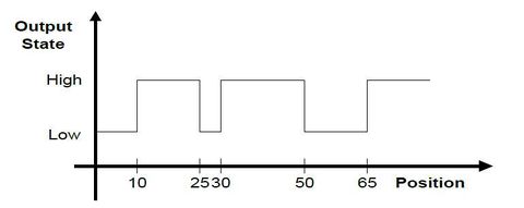
For example: consider the following PLS whose positions are 10, 25, 30, 50, 65, and polarity is 0, as shown in this figure.
As can be seen, the polarity of the first segment (between 10-25) is as indicated by the polarity (1). Enabling the PLS in any other segment will cause the output to be as indicated in the figure.
Output State
A PLS causes an output (digital or virtual) to be triggered when a specified axis position is reached. The initial state of the output will be determined by the PLS polarity property. When the position is reached, the state of the output is toggled. The state is also toggled each time the position is reached, irrespective of the direction of motor travel.
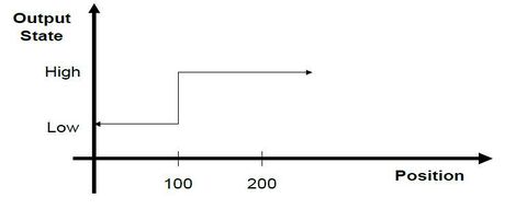
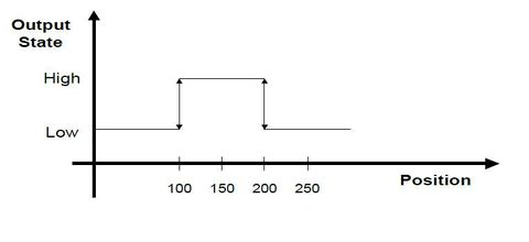
Multiple positions may be specified, in which case the state of the digital output will be toggled as each position is reached. For example, consider the following PLS specification: positions 100 and 200 are specified, and the initial state of the digital output after enabling is 0. The following table illustrates how the state of output changes with changing position.
| Position | Output State |
| 0 | 0 |
| 100 | 1 (Toggle) |
| 150 | 1 (No change) |
| 200 | 0 (Toggle) |
| 210 | 0 (No change yet) |
| 200 | 1 (Toggle again) |
| 150 | 1 (No change) |
| 100 | 0 (Toggle again) |
If the axis position were to oscillate around a specified PLS position, the output would be triggered each time the specified position was crossed.
The initial output state is specified implicitly by the user. The output is set to this state when the PLS is enabled.
PLS Position Data
The PLS position data is stored in a data structure that belongs to the PLS mechanism. This data structure is explicitly created, using the CreatePlsData command.
The PLS data has read/write access. The user must ensure that the PLS position data is monotonic (to allow a PLS to be enabled).
Hysteresis
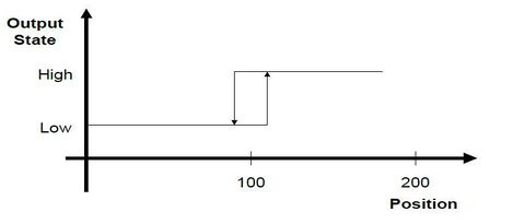
If the axis were to stop on a specified PLS position, the state of the digital output may be continually toggled, due to slight instability in the actual axis position. In this case, a hysteresis value may optionally be specified. The output state will be toggled when the PLS position is reached, and is passed by the hysteresis value. If, as shown in this example, the hysteresis value is 10, then the output will change from Low to High at position 110. It will revert to Low when the position goes down to 90.
Repetition Interval
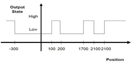
PLS positions may be continually repeated at a specified interval. Thus if a PLS position of 100, for example, is specified with a repetition interval of 2000, then the output state will be toggled at 100, and again at 2100, 4100, and so on, in the positive direction, and at -1900, -3900, and so on in the negative direction.
The repetition interval must be positive, and it must be greater than the absolute value difference between the least and greatest PLS position values. That is:
Repetition Interval > abs(PLS_Pos_Max - PLS_Pos_Min)
Example:
- PLS Position values: -300, 100, 200
- Repetition Interval: 2000
- Polarity: 0
The output state will be toggled at -300, 100, 200, as well as at 1700 (-300 + 2000), 2100 (100+2000), 2200, and at 3700 (-300 + 2000 + 2000) etc. In the negative direction, the output state will be toggled at -1800 (200 - 2000), -1900 (100 - 2000), -2300 (-300 - 2000), -3800 etc.
PLS Constraints
- The number of PLSes is not be limited by the system. It is understood that there is a direct tradeoff between the number of PLSes defined and the system performance.
- The number of PLS positions defined per PLS is not be limited.
- More than one PLS may be defined per axis.
- PLSes are scanned at the motion bus cycle rate.
Enable and Disable
After being defined, a PLS is disabled (output pattern is not generated). The output is set when the PLS is enabled. The output is set to the defined initial state. PLS properties are changed only when the PLS is disabled. Each enabled PLS requires CPU resources. Conserve those resources by disabling the unused PLS(s). PLSEnable controls the status of the PLS:
MyPLS.PlsEnable = ON | OFF
PLSENABLE queries the status of a PLS:
?MyPls.PlsEnable
if(MyPLS.PlsEnable = OFF)
. . .
or drives events:
EventOn MyEvent MyPLS.PlsOutput = ON
PLS Output State
Query the digital output associated with the PLS to query the state of the PLS output.
For example, assume the PLS output is assigned to
SYSTEM.DOUT.1. To determine the output state of the PLS, query the state
of SYSTEM.DOUT.1:
-->?Sys.Dout.1
0 | 1
Example
Step 1
Declare the PLS with COMMON SHARED <PLS name> AS PLS in Config.Prg or at the terminal. You must name the PLS, specify the axis that drives the PLS, and name an output to be controlled by the PLS. For example:
Common Shared MyPLS as PLS A1 System.Dout.1
sets up MyPLS as a PLS driven by axis A1 connected to SYSTEM.DOUT.1. The output can be a digital output (SYSTEM.DOUT.1 through DOUT.20) or it can be one of the virtual outputs (SYSTEM.VOUT.1 through VOUT.32). After the Common Shared as PLS executes, the PLS is disabled. Properties of the PLS are set as:
- A single PLS position exists at 0.
- The initial output polarity is 1.
- PLSREPEAT is set to 0.
- The hysteresis is set to 0.
These properties may be set explicitly, as long as the PLS remains disabled. You can check which output is associated with a given PLS using PLSOUTPUT.
Step 2
Create the PLS data structure and define PLS positions. The number of defined positions is not explicitly limited. A call to CreatePlsData creates an array of n positions that stores the position data. The array is 1- based and an error is generated if you attempt to access an index outside of the array bounds. For example:
CreatePLSData 4 MyPLS
MyPLS.PLSPosition[1] = 1000
MyPLS.PLSPosition[2] = 1100
As a short form, you can use PPOS in place of PlsPosition :
MyPLS.Ppos[3] = 2000
MyPLS.Ppos[4] = 2200
You cannot change PLS positions when the PLS is enabled. Position values must be increasing monotonically.
Step 3
Set the polarity. PLSPOLARITY defaults to OFF, indicating the PLS state should be OFF after the first position. Change PlsPolarity to ON to invert the state.
MyPLS.PLSPolarity = ON
Change PlsPolarity only if the PLS is disabled.
Step 4
Set PlsRepeat . If you want the PLS to repeat, set the value of PLSREPEAT to a non-zero, positive number. For example, to have the PLS repeat every 10,000 position units, enter:
MyPLS.PLSRepeat = 10000
PLSREPEAT defaults to 0, indicating that there is no repetition. Change PLSREPEAT only when the PLS is disabled.
Step 5
Set PlsHysteresis, if the application requires it. Hysteresis is only necessary if the system does stop on or near a PLS position. Normally, a PLSHYSTERESIS of 5 or 10 counts of encoder (converted to position units) or 2 or 3 counts of resolver resolution is sufficient.
MyPLS.PLSHysteresis = 0.01
Step 6
Enable the PLS Enter:
MyPLS.PLSEnable = ON
There are a few other PLS functions you may need:
- Change Polarity
The default output state of a PLS is 0. Change this initial state by modifying PLSPOLARITY.
MyPLS.PLSPolarity = 1
The PLS must be disabled when changing this setting.
- Query the Name
Query the name of the axis driving the PLS:
? MyPLS.PLSAxisName
returns the axis associated with the PLS (A1).
- Disable the PLS
Disable the PLS. For example:
MyPLS.PLSEnable = OFF
You must disable a PLS to change PLS properties. Disabling a PLS also helps conserve CPU resources.
- Delete a PLS
Delete a PLS to remove it from the system only when the PLS is disable and there are no tasks in memory. For example:
DeletePLS MyPLS
Command Set
A PLS is defined using the syntax for variable declaration. The following PLS properties are defined:
- PLS name
- Axis
- Output name
- One or more PLS positions
- Optional initial output state
- Optional repetition interval
- Optional hysteresis setting
PLS Commands
- COMMON | DIM] SHARED <PLS name> AS PLS
- DeletePls
- CreatePlsData
- PLSAxisName
- PlsOutput
- PlsPosition
- PlsPolarity
- PlsRepeat
- PlsHysteresis
- PLSEnable

