Difference between revisions of "Galileo Sphere Robot (GSR) Kinematics"
(Added to Category:Robot Models) |
|||
| (One intermediate revision by one other user not shown) | |||
| Line 1: | Line 1: | ||
| − | {{Languages}} | + | {{Languages|Galileo_Sphere_Robot_(GSR)_Kinematics}} <div class="noprint" id="BackToTop" style="background-color:; position:fixed; bottom:32px; left:95%; z-index:9999; padding:0; margin:0;"> |
| − | =Robot Kinematics for Galileo Sphere Robot= | + | |
| + | <span style="color:blue; font-size:8pt; font-face:verdana,sans-serif; border:0.2em outset:#ceebf7; padding:0.1em; font-weight:bolder; -moz-border-radius:8px;">[[File:TOP2.png|50px|TOP2.png|link=#top]]</span></div> | ||
| + | = Robot Kinematics for Galileo Sphere Robot = | ||
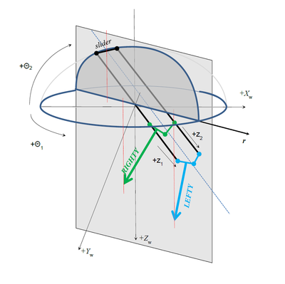
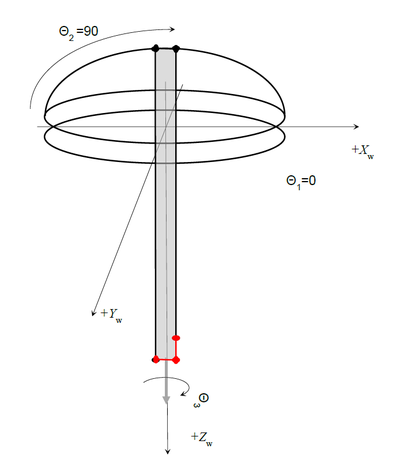
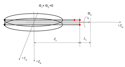
| − | [[ | + | [[File:GSR-SETUP.JPG|RTENOTITLE]] [[File:GSR-SIDE-DRAWINGS.PNG|400px|GSR-SIDE-DRAWINGS.PNG]] [[File:GSR-FRONT-DRAWING.PNG|400px|GSR-FRONT-DRAWING.PNG]] |
| + | | ||
| − | ==Robot Definition as a Group of Axes with a Predefined Point Type== | + | == Robot Definition as a Group of Axes with a Predefined Point Type == |
The robot kinematics will be assigned to a new model type ('''15''') with a '''XYZPR''' (x,y,z, pitch, roll) point type. The following line defines the GALILEO robot as a new system variable: | The robot kinematics will be assigned to a new model type ('''15''') with a '''XYZPR''' (x,y,z, pitch, roll) point type. The following line defines the GALILEO robot as a new system variable: | ||
| − | <pre> | + | <pre>Common Shared GALILEO As Group Axnm = A1 Axnm = A2 Axnm = A3 Axnm = A4 Axnm = A5 model = 15 of '''xyzpr''' |
| − | Common Shared GALILEO As Group Axnm = A1 Axnm = A2 Axnm = A3 Axnm = A4 Axnm = A5 model = 15 of '''xyzpr''' | ||
</pre> | </pre> | ||
| − | ==Kinematics of the Robot == | + | == Kinematics of the Robot == |
| − | [[ | + | [[File:GSR0.PNG|400px|GSR0.PNG]] |
| − | ===Joint Coordinates=== | + | === Joint Coordinates === |
| − | {| border = 1 | + | {| border="1" |
| − | |||
|- | |- | ||
| − | | | + | | Axis name |
| + | | Joint | ||
| + | | Type | ||
| + | | Range | ||
| + | | Units | ||
|- | |- | ||
| − | | | + | | Theta1 |
| + | | J1 | ||
| + | | Rotary axis | ||
| + | | [-180,180] | ||
| + | | deg | ||
|- | |- | ||
| − | | | + | | Theta2 |
| + | | J2 | ||
| + | | Rotary axis | ||
| + | | [-10,90] | ||
| + | | deg | ||
|- | |- | ||
| − | | | + | | Z1 |
| + | | J3 | ||
| + | | Linear | ||
| + | | [Z1min,Z1max] | ||
| + | | mm | ||
|- | |- | ||
| − | |Theta3 | + | | Z2 |
| + | | J4 | ||
| + | | Linear | ||
| + | | [Z2min,Z2max] | ||
| + | | mm | ||
| + | |- | ||
| + | | Theta3 | ||
| + | | J5 | ||
| + | | Rotary axis | ||
| + | | Multi turn | ||
| + | | deg | ||
|} | |} | ||
'''Three Rotary Axes:''' | '''Three Rotary Axes:''' | ||
| − | * theta1 – big horizontal rotary (J1 or joint #1) | + | |
| − | * theta2 – pitch axis (J2 or joint #2) | + | *theta1 – big horizontal rotary (J1 or joint #1) |
| − | * theta3 – tool rotation (J5 or joint #5) | + | *theta2 – pitch axis (J2 or joint #2) |
| + | *theta3 – tool rotation (J5 or joint #5) | ||
'''Two linear axes:''' | '''Two linear axes:''' | ||
| − | |||
| − | |||
| − | |||
| − | + | *Z1 (J3 or joint #3) | |
| − | + | *Z2 (J4 or joint #4) | |
| + | The Z1 is the linear axis without connecting rod. General presentation of the robot joint point in MC-Basic language is (list of numeric expressions inside curly brackets): | ||
<pre>{J1, J2, J3, J4, J5}</pre> | <pre>{J1, J2, J3, J4, J5}</pre> | ||
| − | ===Cartesian Coordinates=== | + | === Cartesian Coordinates === |
| − | Cartesian coordinates (world) of the robot TCP (Tool Center Point) are (Xw, Yw, Zw). Orientation of the robot tool’s Z axis is always expressed as a rotation needed to rotate the Z world (Zw) axis into Z tool (Zt) axis. It can be expressed with 3 Euler angles (Yaw, Pitch, Roll) of the ZYZ order of rotations. | + | Cartesian coordinates (world) of the robot TCP (Tool Center Point) are (Xw, Yw, Zw). Orientation of the robot tool’s Z axis is always expressed as a rotation needed to rotate the Z world (Zw) axis into Z tool (Zt) axis. It can be expressed with 3 Euler angles (Yaw, Pitch, Roll) of the ZYZ order of rotations. '''Yaw Angle:''' Rotating (Xw, Yw, Zw) system around Zw axis into (X1, Y1, Z1) '''Pitch Angle:''' Rotating (X1, Y1, Z1) system around Y1 axis into (X2, Y2, Z2) '''Roll Angle:''' Rotating (X2, Y2, Z2) system around Z2 axis into (X3, Y3, Z3) which coincides to (Xt, Yt, Zt) |
| − | '''Yaw Angle:''' | ||
| − | Rotating (Xw, Yw, Zw) system around Zw axis into (X1, Y1, Z1) | ||
| − | '''Pitch Angle:''' | ||
| − | Rotating (X1, Y1, Z1) system around Y1 | ||
| − | '''Roll Angle:''' | ||
| − | Rotating (X2, Y2, Z2) system around Z2 | ||
As the given robot has only 5 degrees of freedom (DOF) we are reducing the orientation representation to Pitch and Roll angles only. That corresponds to rotations around Y2 (axis obtained after rotating Yw with θ1) and Z3 tools Z axis (in that order). | As the given robot has only 5 degrees of freedom (DOF) we are reducing the orientation representation to Pitch and Roll angles only. That corresponds to rotations around Y2 (axis obtained after rotating Yw with θ1) and Z3 tools Z axis (in that order). | ||
| − | General presentation of the robot Cartesian point in MC-Basic language is | + | General presentation of the robot Cartesian point in MC-Basic language is (list of numeric expressions inside curly brackets preceded with hash sign): |
| − | |||
<pre>#{X, Y, Z, Pitch, Roll}</pre> | <pre>#{X, Y, Z, Pitch, Roll}</pre> | ||
| − | =Geometry= | + | = Geometry = |
The important geometrical parameters of the robot are: | The important geometrical parameters of the robot are: | ||
| − | [[ | + | [[File:GSR1.PNG|400px|GSR1.PNG]] |
List of parameters: | List of parameters: | ||
| − | {| border = 1 | + | |
| − | + | {| border="1" | |
|- | |- | ||
| − | | | + | | Name |
| + | | Units | ||
| + | | Description | ||
| + | | MC-Basic property | ||
|- | |- | ||
| − | | | + | | D1 |
| + | | mm | ||
| + | | Distance between the axes | ||
| + | | <robot>.Link[1][1] | ||
|- | |- | ||
| − | | | + | | D2 |
| + | | mm | ||
| + | | Tool mounting rod | ||
| + | | <robot>.Link[1][2] | ||
|- | |- | ||
| − | | | + | | D3 |
| + | | mm | ||
| + | | Extension rod | ||
| + | | <robot>.Link[1][3] | ||
|- | |- | ||
| − | |B1 | + | | L1 |
| + | | mm | ||
| + | | Tool Length | ||
| + | | <robot>.Link[2][1] | ||
| + | |- | ||
| + | | B1 | ||
| + | | mm | ||
| + | | Vertical (Z) offset of the θ2 rotation center (C2) from the center of θ1-circle (C1). | ||
| + | | <robot>.Link[2][2] | ||
|} | |} | ||
| − | There are two additional parameters that are defined implicitly by defining the zero coordinate | + | There are two additional parameters that are defined implicitly by defining the zero coordinate of the z axes (z1off and z2off). Both z axes should have zero at same line (see picture). These two will include the offset from the axis encoder zero position to the rotation axis of θ2 - including all fixed additional linkages connected to it (not depicted in the picture as they do not alternate the basic robot kinematics). |
| − | of the z axes (z1off and z2off). Both z axes should have zero at same line (see picture). These two will include the offset from the axis encoder zero position to the rotation axis of θ2 | ||
{{Note/Important|The assumption is that the robot has symmetrical setup. The tool flange is in the middle of D2 link and the center of rotation of the theta2 is in the middle of the theta1 circle. It is crucial to have these two requirements fulfilled, if not the kinematics relations will be invalid. | {{Note/Important|The assumption is that the robot has symmetrical setup. The tool flange is in the middle of D2 link and the center of rotation of the theta2 is in the middle of the theta1 circle. It is crucial to have these two requirements fulfilled, if not the kinematics relations will be invalid. | ||
}} | }} | ||
| − | =Singularities= | + | = Singularities = |
Theoretically speaking there are two singularities of these kinematics, let’s call them roll-singularity and linkage-singularity (these names are just arbitrarily given as we need somehow to denote them), but we will handle just one and the other will be not available to the user. Here is the explanation: | Theoretically speaking there are two singularities of these kinematics, let’s call them roll-singularity and linkage-singularity (these names are just arbitrarily given as we need somehow to denote them), but we will handle just one and the other will be not available to the user. Here is the explanation: | ||
| − | ==Roll-singularity== | + | == Roll-singularity == |
| − | + | [[File:GSR-CONFIG.PNG|400px|GSR-CONFIG.PNG]] | |
| − | [[ | ||
This type of singularity happens when θ<sub>1</sub> and θ<sub>3</sub> are co-linear. Their sum (θ<sub>1</sub> + θ<sub>3</sub>) builds the Cartesian roll angle and any combination of these two numbers will represent the same roll angle. | This type of singularity happens when θ<sub>1</sub> and θ<sub>3</sub> are co-linear. Their sum (θ<sub>1</sub> + θ<sub>3</sub>) builds the Cartesian roll angle and any combination of these two numbers will represent the same roll angle. | ||
| − | ==Linkage-singularity== | + | == Linkage-singularity == |
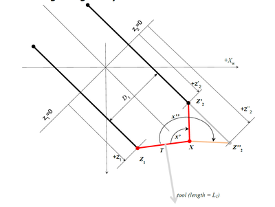
| − | [[ | + | [[File:GSR-RSING.PNG|400px|GSR-RSING.PNG]] |
| − | It is a typical four-bar mechanism singularity where for the same position of Z1X segment there are two solutions for Z2 point. | + | It is a typical four-bar mechanism singularity where for the same position of Z1X segment there are two solutions for Z2 point. In order to avoid problems with this type of singularity only solutions with minimal x angle will be taken (x’ angle in the drawing). |
| − | |||
| − | =Configuration Flags= | + | = Configuration Flags = |
Actually there should be two configuration flags in the system. But, as the one of the configuration is not allowed, only one (ARM) is made available (accessible for reading and writing) to the user. | Actually there should be two configuration flags in the system. But, as the one of the configuration is not allowed, only one (ARM) is made available (accessible for reading and writing) to the user. | ||
| − | [[ | + | [[File:GSR-LSING.PNG|400px|GSR-LSING.PNG]] |
| − | The Arm configuration flag is defined according to the following reasoning: | + | The Arm configuration flag is defined according to the following reasoning: |
If the tool-tip is on the same side as the θ<sub>2</sub> slider it is '''RIGHTY'''; otherwise it is '''LEFTY''' | If the tool-tip is on the same side as the θ<sub>2</sub> slider it is '''RIGHTY'''; otherwise it is '''LEFTY''' | ||
| − | Or: | + | Or: |
| − | Arm is '''LEFTY''' if r > 0<br> | + | Arm is '''LEFTY''' if r > 0<br/> Arm is '''RIGHTY''' if r < 0 |
| − | Arm is '''RIGHTY''' if r < 0 | ||
| + | In the MC-Basic language it is: | ||
| − | + | *[[MC-Basic:robot.ARMCMD|<robot>.Acmd]] for the commanded configuration | |
| + | *[[MC-Basic:robot.ARMFBK|<robo>.Afbk]] for the current(feedback) configuration | ||
| − | + | = Typical Robot Poses = | |
| − | |||
| − | |||
Here is a list of some typical poses for a better understanding of the workspace coordinates. They do not necessary represent the feasible positions of the robot (due to some axis position limitations) but they are good examples to finalize and test robot kinematics definitions. | Here is a list of some typical poses for a better understanding of the workspace coordinates. They do not necessary represent the feasible positions of the robot (due to some axis position limitations) but they are good examples to finalize and test robot kinematics definitions. | ||
| − | [[ | + | [[File:GSR-POS0.PNG|400px|GSR-POS0.PNG]] |
| − | • Horizontal position, pitch angle = 90 degrees: | + | • Horizontal position, pitch angle = 90 degrees: {0,0,Z1,Z2-D3,0} #{Z1+L1,B1,-90,0} |
| − | {0,0,Z1,Z2-D3,0} #{Z1+L1,B1,-90,0} | ||
| − | • Same pose rotating theta 3 – directly translated into roll angle. | + | • Same pose rotating theta 3 – directly translated into roll angle. {0,0,Z1,Z2-D3,45} #{Z1+L1,B1,-90,45} {0,0,Z1,Z2-D3,-45} #{Z1+L1,B1,-90,-45} |
| − | {0,0,Z1,Z2-D3,45} #{Z1+L1,B1,-90,45} | ||
| − | {0,0,Z1,Z2-D3,-45} #{Z1+L1,B1,-90,-45} | ||
| + | [[File:GSR-POS1.PNG|400px|GSR-POS1.PNG]] | ||
| − | + | Horizontal position, pitch angle = ±90 degrees: {90,0,Z1,Z1-D3,0} #{0,-(Z1+L1),B1,-90,0} {-90,0,Z1,Z1-D3,0} #{0,+(Z1+L1),B1,-90,0} | |
| + | [[File:GSR-POS2.PNG|400px|GSR-POS2.PNG]] | ||
| − | + | • Singular point: {0,90,Z1,Z1-D3,0} #{0,0,B1+(Z1+L1),0,0} {R,90,Z1,Z1-D3,-R} #{0,0, B1+ (Z1+L1),0,0} for any R! | |
| − | {90 | ||
| − | { | ||
| − | + | == GSR light v2 sezione T2 Z out == | |
| − | + | [[File:GSR-LV02T2ZOUT.PNG|400px|GSR-LV02T2ZOUT.PNG]] | |
| − | + | <pre>-->move {0,90,386+76,386,0} | |
| − | |||
| − | |||
| − | |||
| − | |||
| − | |||
| − | [[ | ||
| − | |||
| − | <pre> | ||
| − | -->move {0,90,386+76,386,0} | ||
-->?setpoint | -->?setpoint | ||
#{-7.41629e-14 , 0 , 743 , 0 , 0} | #{-7.41629e-14 , 0 , 743 , 0 , 0} | ||
| Line 167: | Line 190: | ||
</pre> | </pre> | ||
| + | | ||
| − | ==GSR light v2 sezione T2 Z in== | + | == GSR light v2 sezione T2 Z in == |
| − | |||
| − | |||
| − | |||
| + | [[File:GSR-LV02T2ZIN.PNG|400px|GSR-LV02T2ZIN.PNG]] | ||
<pre>-->move {0,90,232+76,232,0} | <pre>-->move {0,90,232+76,232,0} | ||
-->?setpoint | -->?setpoint | ||
| Line 179: | Line 201: | ||
</pre> | </pre> | ||
| − | ==GSR light v02 Z.in T3.60 == | + | == GSR light v02 Z.in T3.60 == |
| − | [[ | + | [[File:GSR-V02ZINT360.PNG|400px|GSR-V02ZINT360.PNG]] |
| − | + | <pre>-->moves {0,90,113.3+373,373,0} | |
| − | <pre> | ||
| − | -->moves {0,90,113.3+373,373,0} | ||
-->?setpoint | -->?setpoint | ||
#{60.8857 , 0 , 730.64 , -29.986 , 0} | #{60.8857 , 0 , 730.64 , -29.986 , 0} | ||
| Line 191: | Line 211: | ||
</pre> | </pre> | ||
| + | | ||
| − | ==GSR light v02 Z.out T3.60 == | + | == GSR light v02 Z.out T3.60 == |
| − | [[ | + | [[File:GSR-V02ZOUTT360.PNG|400px|GSR-V02ZOUTT360.PNG]] |
| − | + | <pre>-->moves {0,90,230+373,230+373-113.3,0} | |
| − | <pre> | ||
| − | -->moves {0,90,230+373,230+373-113.3,0} | ||
-->?setpoint | -->?setpoint | ||
#{60.8857 , 0 , 847.34 , -29.986 , 0} | #{60.8857 , 0 , 847.34 , -29.986 , 0} | ||
| Line 205: | Line 224: | ||
</pre> | </pre> | ||
| + | | ||
| − | ==GSR light v02 Z.in T3.135 == | + | == GSR light v02 Z.in T3.135 == |
| − | |||
| − | |||
| − | <pre> | + | [[File:GSR-V02ZINT3135.PNG|400px|GSR-V02ZINT3135.PNG]] |
| − | -->move {0,90,76+373,76+373 - 18.9,0} | + | <pre>-->move {0,90,76+373,76+373 - 18.9,0} |
-->?setpoint | -->?setpoint | ||
#{-104.514 , 0 , 718.183 , 45.022 , 0} | #{-104.514 , 0 , 718.183 , 45.022 , 0} | ||
| Line 219: | Line 237: | ||
</pre> | </pre> | ||
| − | ==GSR light v02 Z.in T3.150 == | + | == GSR light v02 Z.in T3.150 == |
| − | |||
| − | |||
| − | <pre> | + | [[File:GSR-V02ZINT3150.PNG|400px|GSR-V02ZINT3150.PNG]] |
| − | -->move {0,90,76+373,76+373,0} | + | <pre>-->move {0,90,76+373,76+373,0} |
-->?setpoint | -->?setpoint | ||
#{-133.315 , 0 , 696.909 , 60 , 0} | #{-133.315 , 0 , 696.909 , 60 , 0} | ||
| Line 231: | Line 247: | ||
</pre> | </pre> | ||
| − | ==GSR light v02 Z.in T3.180 == | + | == GSR light v02 Z.in T3.180 == |
| − | + | [[File:GSR-V02ZINT3180.PNG|400px|GSR-V02ZINT3180.PNG]] | |
| − | [[ | + | <pre>-->move {0,90,76+373,76+373+76,0} |
| − | |||
| − | <pre> | ||
| − | -->move {0,90,76+373,76+373+76,0} | ||
-->?setpoint | -->?setpoint | ||
#{-170 , 0 , 636 , 90 , 0} | #{-170 , 0 , 636 , 90 , 0} | ||
| Line 246: | Line 259: | ||
</pre> | </pre> | ||
| + | {{Note|At this point we have the linkage singularity.}} | ||
| − | + | [[Category:Robot Models]] | |
Latest revision as of 05:37, 8 April 2022
| Language: | English • 中文(简体) |
|---|
Contents
Robot Kinematics for Galileo Sphere Robot
Robot Definition as a Group of Axes with a Predefined Point Type
The robot kinematics will be assigned to a new model type (15) with a XYZPR (x,y,z, pitch, roll) point type. The following line defines the GALILEO robot as a new system variable:
Common Shared GALILEO As Group Axnm = A1 Axnm = A2 Axnm = A3 Axnm = A4 Axnm = A5 model = 15 of '''xyzpr'''
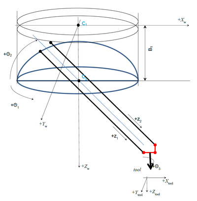
Kinematics of the Robot
Joint Coordinates
| Axis name | Joint | Type | Range | Units |
| Theta1 | J1 | Rotary axis | [-180,180] | deg |
| Theta2 | J2 | Rotary axis | [-10,90] | deg |
| Z1 | J3 | Linear | [Z1min,Z1max] | mm |
| Z2 | J4 | Linear | [Z2min,Z2max] | mm |
| Theta3 | J5 | Rotary axis | Multi turn | deg |
Three Rotary Axes:
- theta1 – big horizontal rotary (J1 or joint #1)
- theta2 – pitch axis (J2 or joint #2)
- theta3 – tool rotation (J5 or joint #5)
Two linear axes:
- Z1 (J3 or joint #3)
- Z2 (J4 or joint #4)
The Z1 is the linear axis without connecting rod. General presentation of the robot joint point in MC-Basic language is (list of numeric expressions inside curly brackets):
{J1, J2, J3, J4, J5}
Cartesian Coordinates
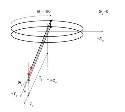
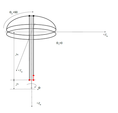
Cartesian coordinates (world) of the robot TCP (Tool Center Point) are (Xw, Yw, Zw). Orientation of the robot tool’s Z axis is always expressed as a rotation needed to rotate the Z world (Zw) axis into Z tool (Zt) axis. It can be expressed with 3 Euler angles (Yaw, Pitch, Roll) of the ZYZ order of rotations. Yaw Angle: Rotating (Xw, Yw, Zw) system around Zw axis into (X1, Y1, Z1) Pitch Angle: Rotating (X1, Y1, Z1) system around Y1 axis into (X2, Y2, Z2) Roll Angle: Rotating (X2, Y2, Z2) system around Z2 axis into (X3, Y3, Z3) which coincides to (Xt, Yt, Zt)
As the given robot has only 5 degrees of freedom (DOF) we are reducing the orientation representation to Pitch and Roll angles only. That corresponds to rotations around Y2 (axis obtained after rotating Yw with θ1) and Z3 tools Z axis (in that order).
General presentation of the robot Cartesian point in MC-Basic language is (list of numeric expressions inside curly brackets preceded with hash sign):
#{X, Y, Z, Pitch, Roll}
Geometry
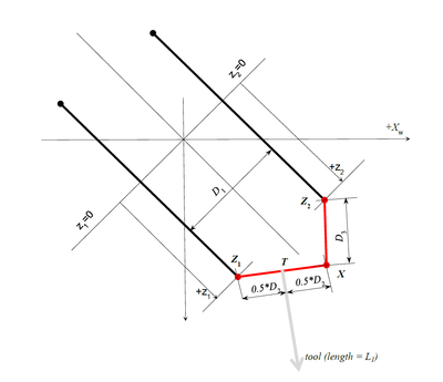
The important geometrical parameters of the robot are:
List of parameters:
| Name | Units | Description | MC-Basic property |
| D1 | mm | Distance between the axes | <robot>.Link[1][1] |
| D2 | mm | Tool mounting rod | <robot>.Link[1][2] |
| D3 | mm | Extension rod | <robot>.Link[1][3] |
| L1 | mm | Tool Length | <robot>.Link[2][1] |
| B1 | mm | Vertical (Z) offset of the θ2 rotation center (C2) from the center of θ1-circle (C1). | <robot>.Link[2][2] |
There are two additional parameters that are defined implicitly by defining the zero coordinate of the z axes (z1off and z2off). Both z axes should have zero at same line (see picture). These two will include the offset from the axis encoder zero position to the rotation axis of θ2 - including all fixed additional linkages connected to it (not depicted in the picture as they do not alternate the basic robot kinematics).
| IMPORTANT | |
| The assumption is that the robot has symmetrical setup. The tool flange is in the middle of D2 link and the center of rotation of the theta2 is in the middle of the theta1 circle. It is crucial to have these two requirements fulfilled, if not the kinematics relations will be invalid. |
Singularities
Theoretically speaking there are two singularities of these kinematics, let’s call them roll-singularity and linkage-singularity (these names are just arbitrarily given as we need somehow to denote them), but we will handle just one and the other will be not available to the user. Here is the explanation:
Roll-singularity
This type of singularity happens when θ1 and θ3 are co-linear. Their sum (θ1 + θ3) builds the Cartesian roll angle and any combination of these two numbers will represent the same roll angle.
Linkage-singularity
It is a typical four-bar mechanism singularity where for the same position of Z1X segment there are two solutions for Z2 point. In order to avoid problems with this type of singularity only solutions with minimal x angle will be taken (x’ angle in the drawing).
Configuration Flags
Actually there should be two configuration flags in the system. But, as the one of the configuration is not allowed, only one (ARM) is made available (accessible for reading and writing) to the user.
The Arm configuration flag is defined according to the following reasoning:
If the tool-tip is on the same side as the θ2 slider it is RIGHTY; otherwise it is LEFTY
Or:
Arm is LEFTY if r > 0
Arm is RIGHTY if r < 0
In the MC-Basic language it is:
- <robot>.Acmd for the commanded configuration
- <robo>.Afbk for the current(feedback) configuration
Typical Robot Poses
Here is a list of some typical poses for a better understanding of the workspace coordinates. They do not necessary represent the feasible positions of the robot (due to some axis position limitations) but they are good examples to finalize and test robot kinematics definitions.
• Horizontal position, pitch angle = 90 degrees: {0,0,Z1,Z2-D3,0} #{Z1+L1,B1,-90,0}
• Same pose rotating theta 3 – directly translated into roll angle. {0,0,Z1,Z2-D3,45} #{Z1+L1,B1,-90,45} {0,0,Z1,Z2-D3,-45} #{Z1+L1,B1,-90,-45}
Horizontal position, pitch angle = ±90 degrees: {90,0,Z1,Z1-D3,0} #{0,-(Z1+L1),B1,-90,0} {-90,0,Z1,Z1-D3,0} #{0,+(Z1+L1),B1,-90,0}
• Singular point: {0,90,Z1,Z1-D3,0} #{0,0,B1+(Z1+L1),0,0} {R,90,Z1,Z1-D3,-R} #{0,0, B1+ (Z1+L1),0,0} for any R!
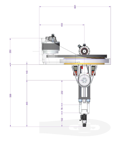
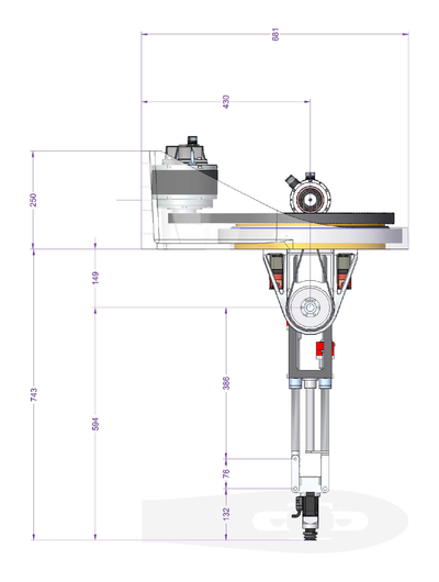
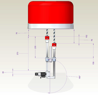
GSR light v2 sezione T2 Z out
-->move {0,90,386+76,386,0}
-->?setpoint
#{-7.41629e-14 , 0 , 743 , 0 , 0}
-->
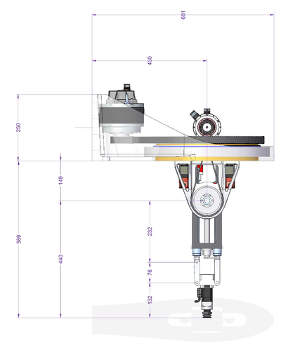
GSR light v2 sezione T2 Z in
-->move {0,90,232+76,232,0}
-->?setpoint
#{-2.26485e-14 , 0 , 589 , 0 , 0}
-->
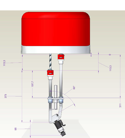
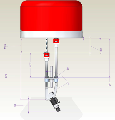
GSR light v02 Z.in T3.60
-->moves {0,90,113.3+373,373,0}
-->?setpoint
#{60.8857 , 0 , 730.64 , -29.986 , 0}
-->?113.3+373+95+149
730.3
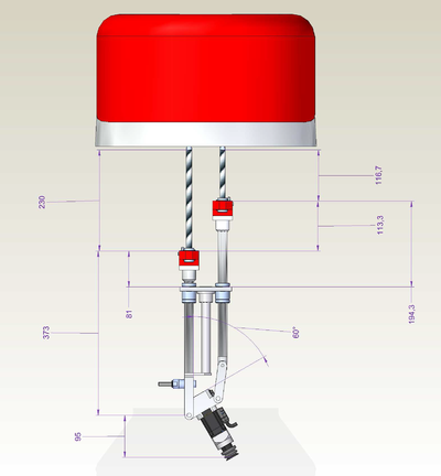
GSR light v02 Z.out T3.60
-->moves {0,90,230+373,230+373-113.3,0}
-->?setpoint
#{60.8857 , 0 , 847.34 , -29.986 , 0}
-->?230+373+95+149
847
-->
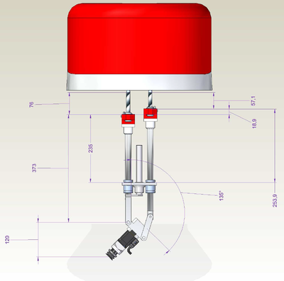
GSR light v02 Z.in T3.135
-->move {0,90,76+373,76+373 - 18.9,0}
-->?setpoint
#{-104.514 , 0 , 718.183 , 45.022 , 0}
-->?120+373+76+149
718
-->
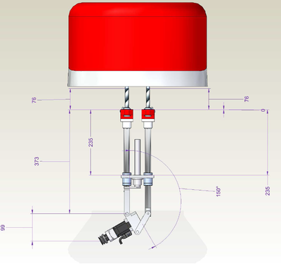
GSR light v02 Z.in T3.150
-->move {0,90,76+373,76+373,0}
-->?setpoint
#{-133.315 , 0 , 696.909 , 60 , 0}
-->?99+373+76+149
697
GSR light v02 Z.in T3.180
-->move {0,90,76+373,76+373+76,0}
-->?setpoint
#{-170 , 0 , 636 , 90 , 0}
-->?38+373+76+149
636
-->
| NOTE | |
| At this point we have the linkage singularity. |

