Difference between revisions of "Single Axis Motion"
m (Text replace - "motion-bus" to "motion bus") |
(BackToTop button) |
||
| (3 intermediate revisions by one other user not shown) | |||
| Line 1: | Line 1: | ||
| + | <div id="BackToTop" class="noprint" style="background-color:; position:fixed; bottom:32px; left:95%; z-index:9999; padding:0; margin:0;"> | ||
| + | <span style="color:blue; font-size:8pt; font-face:verdana,sans-serif; border:0.2em outset:#ceebf7; padding:0.1em; font-weight:bolder; -moz-border-radius:8px; "> | ||
| + | [[Image:TOP2.png|50px|link=#top]] </span></div> | ||
| + | {{Languages|Single_Axis_Motion}} | ||
{{Out-of-date}} | {{Out-of-date}} | ||
= Introduction = | = Introduction = | ||
Latest revision as of 09:01, 8 August 2017
| Language: | English • 中文(简体) |
|---|
| IMPORTANT | |
| This entry is outdated and requires revision. |
Introduction
The softMC supports three main types of motion:
- Single-axis motion
- Master-Slave motion
- Multiple-axes motion
A motion generator controls all motion in the softMC. This software device receives commands from softMC tasks and produces position and velocity commands for the drives every servo cycle. The two main single-axis motion commands are JOG and MOVE. The softMC also provides ways to synchronize the execution of motion commands as well as changing motion profiles on-the-fly. In addition, the softMC provides multiple modes for starting and stopping motion.
All motion commands are subject to inherent system delays due to motion bus communications. One cycle time is required to transmit a command. A second cycle time is required to receive the position feedback. Thus, the minimum system delay is at least 2 motion bus cycles (typically 4 for EtherCAT). If microinterpolation is enabled in the drive, there is an additional delay of 1 cycle time. Additional, indeterminate, delays may result from the servo system dependent on drive tuning and kinetics of the mechanical system.
Motion Generator
The basis of all motion in the softMC is the motion generator. When you issue a motion command such as JOG or MOVE to an axis, a motion generator is created in software. That motion generator controls the position and velocity commands of the axis specified in the move command. At regular intervals (normally 2 or 4 ms), the motion generator updates these commands. At the end of motion, the motion generator is terminated. The figure below shows the normal operation of a motion generator.
Motion Conditions
Several conditions must be met before the softMC generates motion:
The controlling task must attach to the controlled axis.
The controlled axis must be enabled.
The system and axis motion flags must be enabled.
Before a task can send motion commands to an axis, the axis must be attached to the task. Attaching is also required for gearing. This prevents other tasks from attempting to control the axis. To attach an axis, issue ATTACH from the controlling task:
Program
Attach A1
If no other task is attached to the axis, the axis is immediately attached. If another task has already attached the axis, an error is generated. A TRY CATCH can be used to wait for an axis to be unattached.
As long as the task has the axis attached, no other task can control the axis. When a task is finished with an axis, it should detach the axis:
Detach A1
If you issue DETACH while profile motion for that axis is in progress, DETACH delays execution until that motion is complete. If a task ends with some axes still attached, all axes are automatically detached.
One exception for the requirement that an axis be attached is if the motion command is issued from the terminal window. In this case, assuming the axis is not attached by any other task, the axis is automatically attached to the terminal window for the duration of the motion command.
Enable the drive by typing the following commands in the terminal window:
System.Enable = ON
A1.Enable = ON
Enable is also necessary for simulated axis although there is no drive connected.
There are two other signals that are required to enable the drive: DRIVEON and HALTRESTART. These signals are normally ON. These signals are kept to comply with SERCOS. They shall not be used by softMC programs in non-SERCOS applications.
More details about access to drive control bits can be found here:
- Drive Control Bits - Implementation of Drive Control Bits under EtherCAT
The last step in preparing a system for motion is turning on the motion flags. There are two motion flags which must be on: the system motion flag and the axis motion flag. For example:
System.Motion = ON
A1.Motion = ON
These lines of code are included in the ControlStudio auto setup program.
In many applications, a hardware switch is tied to the motion flag. The softMC does not have a hardware motion input. However, you can use softMC events to create this function. The following example shows a task that uses input external data input 1 to control the system motion flag:
Program
OnEvent MOTION_ON System.DIn.1 = ON
 System.Motion = ON
End OnEvent
OnEvent MOTION_OFF System.DIn.1 = OFF
 System.Motion = OFF
End OnEvent
End Program
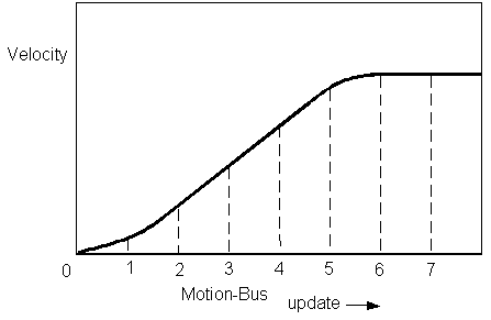
The purpose of the motion generators is to convert motion commands (JOG or MOVE) into a regularly updated series of position and velocity commands. That series is called a motion profile. The position and velocity commands are sent via motion bus (EtherCAT, CAN, SERCOS) to the controlled drive. All the servo loops (position, velocity, and current) are closed in the drives. The next figure shows the profile for the velocity portion of a JOG command.
The profile must be updated at regular intervals. The softMC usually updates the profile every motion bus cycle (1 ms update rate, if possible when the drive supports this update rate). The cyclic data between softMC and the drives also gets longer with more axes, therefore EtherCAT applications with more than 20 axes may require reconfiguration of PDOs in order to remove unused objects from PDOs. TBD.
Motion Buffering
The motion generator for each axis can process only one motion command at a time because the axis can process only one position or velocity command. However, you can send a second motion command to the generator where it is held until the current motion command is complete (motion buffering).
Motion buffering is controlled with STARTTYPE. If STARTTYPE is set to GENERATORCOMPLETED, the buffered profile starts immediately after the current profile is complete. If STARTTYPE is set to INPOSITION, the buffered profile starts after the current profile is complete and the position feedback has settled out to the position command. In both cases, the second command is held in the motion generator to begin immediately after the appropriate conditions are met.
You can also specify that the motion generator not buffer, but process the new motion command immediately. This is useful when you want to make realtime changes to the profile (changing the end position of the current command). For this, set STARTTYPE to IMMEDIATE (IMMED) or SUPERIMMEDIATE (SIMM).
Override versus Permanent
Axes have numerous properties such as acceleration and deceleration. These properties are normally set directly:
ConveyorAxis.Acc = 100
This setting is permanent. It persists until the next time the property is assigned a value. For convenience, the softMC also supports override values where the property is set as part of a command. In this case, the setting is used only for the current command.
For example:
ConveyorAxis.Acc = 100
Jog ConveyorAxis 1000 ACC = 10
Even though the acceleration rate of the conveyor axis is specified at 100 in the first line, JOG accelerates at 10 (the override value). Motion commands that do not specify an override acceleration rate accelerate at the permanent value.
Override values are used extensively in motion commands. The values that can be overridden are specified below as well as in the Reference Manual.
Acceleration Profile
The single-axis motion commands, MOVE and JOG, produce acceleration curves that are limited by:
ACCELERATION (ACC)
DECELERATION (DEC)
SMOOTHFACTOR (SMOOTH)
Limit ACCELERATION and DECELERATION to less than the acceleration capabilities of the motor and load. SMOOTH helps limit or reduce mechanical wear on the machine by smoothing motion.
There are two types of acceleration profiles – sinus-curve profile and trapezoidal profile. In the sinus profile the acceleration is smoothly increased while in the trapezoidal profile, the acceleration is increases in one sample. Setting the acceleration increasing smoothness is done using SMOOTHFACTOR.
Jog
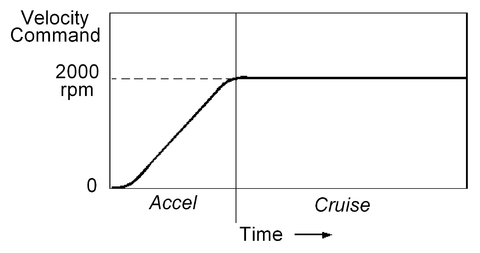
When you want to command the motor to move at a constant velocity independent of the current position, use JOG. Velocity can be negative to produce motion in the reverse direction. For example:
Jog ConveyorAxis 2000
produces this profile:
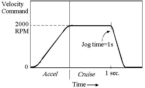
You can optionally limit the amount of time JOG runs using TIMEJOG. TIMEJOG must be placed on the same line with JOG. TIMEJOG is specified in milliseconds and includes acceleration time. Deceleration starts when the time expires. When TIMEJOG is -1, JOG continues indefinitely. TIMEJOG defaults to ‑1. For example:
Jog ConveyorAxis 2000 TimeJog = 1000
produces the profile below.
The following axis properties can be overridden as part of JOG:
TIMEJOG
ACCELERATION
DECELERATION
SMOOTHFACTOR
JERK
VELOCITYRATE
ACCELERATIONRATE
DECELERATIONRATE
JERKRATE
Stop
STOP stops motion in the motion buffer. In the command, you must specify the axis. For example:
Stop ConveyorAxis
Normally, STOP is set to stop motion immediately at the rate of DECELERATIONMAX. However, you can modify the effects of STOP with STOPTYPE. STOPTYPE can take three values:
StopType = Immediate or IMMEDStop axis immediately at DECELERATIONMAX rate
StopType = EndMotionStop axis at end of current motion command and clear buffered motion
StopType = AbortStop the current motion immediately without ability to restore the stopped movements. Only the current motion command is stopped, the commands coming after are generated.
STOPTYPE defaults to IMMED. If STOPTYPE = ENDMOTION, the current move is completed before STOP is executed. For JOG with TIMEJOG = -1 (continue indefinitely), STOPTYPE = ENDMOTION has no meaning because JOG never ends. During STOP, the current and pending movements in the buffer are stored to allow recovery of these movement using PROCEED.
STOP uses the modal maximum deceleration and maximum jerk. STOPTYPE is overridden as part of a STOP.
Proceed
When a task stops motion in axes it has attached, restarting the motion is simple. The logic is contained inside the task. However, when motion is stopped from another task, the situation is more complex. For example, the system should prevent any task from restarting the motion except the task that stopped it. To control the restarting of motion after a STOP, the softMC supports PROCEED.
PROCEED has two purposes: to enhance safety and to allow motion to continue along the original path. The safety enhancement is provided by not allowing motion on an axis to restart without the task that stopped the motion issuing a PROCEED. The path control is provided by <''axis''>.PROCEEDTYPE. PROCEEDTYPE can be set in one of three modes: CONTINUE, NEXT MOTION, and CLEARMOTION. The key rules of operation are:
- When a task stops the motion of axes to which it is attached, a PROCEED is allowed, but not required.
- When STOP is issued from the terminal window and the axis being stopped is attached to a task, motion is stopped and the task is suspended upon execution of the next motion or DETACH. The task and the motion it commands can restart only after a PROCEED is issued from the terminal window. Motion is commanded from the terminal window before PROCEED is issued.
- When STOP is issued from one task and the axis being stopped is attached to another task, motion is stopped and the task is suspended upon execution of the next motion or DETACH. The task and the motion it commands restart only after PROCEED is issued from the task that stopped motion. Motion cannot be commanded from the task that stopped motion.
- When STOP is issued from the terminal window for a command given from the terminal window, the motion is stopped and cannot proceed. In this case, the only available proceed type is CLEARMOTION from the terminal.
There are three ways for PROCEED to restart motion. Use PROCEEDTYPE to specify how the motion generator should proceed:
ProceedType = ContinueThis causes the motion generator to continue the motion command that was stopped followed by the pending motion in the stopped buffer.
ProceedType = NextMotionThis causes the motion generator to abort the current move and go directly to the move in the stopped motion buffer.
ProceedType = ClearMotionThis clears the motion buffer. All motion commands in the stopped motionbuffer are aborted. This is the default.
Move
MOVE is the most common of point-to-point moves. The basic move is a three-segment motion:
Accelerate Go from zero speed to VelocityCruise
Cruise Continue at VelocityCruise.
Decelerate Go from VelocityCruise to VelocityFinal
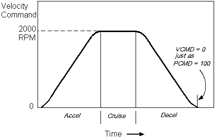
The critical part of a three-segment move is starting the deceleration at the right time so that the motor speed becomes zero (if VELOCITYFINAL = 0) just as the position command reaches the final position. For example, the following command:
Move ConveyorAxis 100 VCruise = 2000
produces the next profile.
Position Final and Incremental Versus Absolute Moves
POSITIONFINAL (the end of a move), is always specified in MOVE. The meaning of PFINAL depends on ABSOLUTE (ABS). This allows point-to-point moves to be specified two ways:
Absolute Moves (Absolute = TRUE)Final position is specified as actual motor position at the end of the move. The final position is equal to PFINAL.
Incremental (Absolute = FALSE)Final position is referenced to the start position. The final position is equal to the sum of PFINAL and PCMD from the start of the move. So:
CutAxis.Absolute = TRUE
Move CutAxis 100
moves CutAxis to position 100. On the other hand:
CutAxis.Absolute = FALSE
Move CutAxis 100
moves CutAxis a distance of 100 units from the current position.
ABSOLUTE defaults to FALSE. You can change ABSOLUTE at any time, although the effect does not take place until you issue the next MOVE.
Settling Time
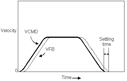
The softMC actively watches to see if axes are settled into position. In almost all applications, the motor position feedback is slightly delayed from the position command. After a move is complete, some time is required for the actual position to settle out to the commanded position; this time is called settling time.
Consider the point-to-point move shown below. The VELOCITYCOMMAND (VCMD) is shown in solid line and VELOCITYFEEDBACK (VFB) is shown in thin line. The area between the two curves is the following error. As you can see, it takes a small amount of time at the end of the move for VFB to settle out to zero. The actual amount of time required for this varies from one system to another. Higher bandwidth systems have shorter settling times, but all systems need some time to settle. Typical times range from a few milliseconds to tens of milliseconds.
Ideally, settling time allows the motor to move to approach zero position error. However, you must allow for the condition where the position error never quite reaches zero. On the softMC , you specify how low you consider to be low enough with <''axis''>.POSITIONERRORSETTLE (<''axis''>.PESETTLE):
CutAxis.PESettle = 0.01
After the motion generator has completed a move which ends with zero speed, it actively monitors the position error on the axis to see when it is between ±PESETTLE.
In some applications, you must ensure that the position error remains below PESETTLE for a specified period of time before the axis is considered settled. The softMC allows you to specify this time period with <''axis''>.TIMESETTLE (given in milliseconds). TIMESETTLEMAX sets the maximum time allowed for the axis to settle. If the position error exceeds PESETTLE during this time, the timer is reset. If position error is within the PESETTLE range for the time specified by TSETTLE, the <''axis''>.ISSETTLED flag is TRUE (1). Otherwise, it is FALSE(0).
Point-to-Point Moves
When the motion buffer is empty, point-to-point moves begin immediately. If you need to delay the start of the next motion command, you have two options: use DELAY to insert a fixed delay time, or use STARTTYPE to delay depending on a condition.
Use DELAY to force the motion generator to wait a fixed period of time between moves. For example:
Move MainAxis 100
Delay 1000
Move MainAxis 200
A 1 second delay is forced between the two moves. DELAY has units of milliseconds and must be greater than zero. DELAY does not delay the execution of your program. If you want to delay your program, use SLEEP.
If you want to delay the start of a new move until a condition has been met by the previous move, use STARTTYPE. There are four choices:
StartType = GeneratorCompleted (GCom)When STARTTYPE = GCOM, the new move starts as soon as the motion generator has completed the motion for the current move. GENERATORCOMPLETED is constant equal to 3. This command incurs a system delay of 2 SERCOS cycle times.
StartType = InPosition (InPos)When STARTTYPE = INPOS, the motion generator delays executing the new motion command until the current move has completed and the position error is settled to near zero. INPOSITION is constant equal to 2. This command is not subject to additional system delays, but any delay associated with the command is due to user-specified parameters for settling time.
StartType = Immediate (Immed)When STARTTYPE = IMMED, the new move overwrites the current move. Use this when making realtime changes to the profile such as changing the end-point of the current move without bringing the system to rest. For example, registration applications frequently use this function. IMMEDIATE is constant equal to 1. This command incurs a system delay of 5 SERCOS cycle times each execution. This time is required to blend the previous move with the new move.
StartType = SuperImmediate (Simm)SUPERIMMEDIATE is a variation of IMMEDIATE. The main difference is that SUPERIMMEDIATE eliminates the 5 SERCOS cycles delay by doing pre-calculation online, rather than offline in the motion manager. SUPERIMMEDIATE is constant equal to 5. The numbers of SUPERIMMEDIATE changes at a time in the system is limited by the load of the system and the type of move. SUPERIMMEDIATE is best used for short, high-speed movements.
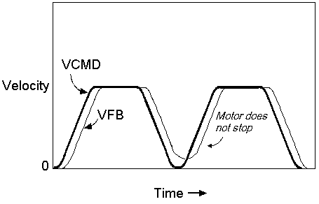
When chaining multiple moves which all end at zero speed, you normally want STARTTYPE = INPOS. This forces the motion generator to wait for the position to settle out before starting the next move. If the position profile starts too soon on the second move, the motor may never come to rest. For example, the next figure shows this problem when STARTTYPE is incorrectly set to GCOM rather than INPOS.
As you can see, the motor speed never gets to zero because the second move takes the velocity command positive before the velocity feedback settles to zero.
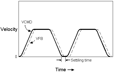
Normally, the desired performance is for the velocity to reach zero before the second move starts. To do this, the controller needs to wait for the axis position error to be settled before starting the second move. This is done by setting STARTTYPE to INPOS. This is shown in the following figure.
As you can see, the motor comes to rest because the softMC waits for the following error to be small enough before proceeding to the next command.
MainAxis.PESettle = 0.01
MainAxis.Tsettle = 10
Move MainAxis 100Move MainAxis 200 StartType=InPos
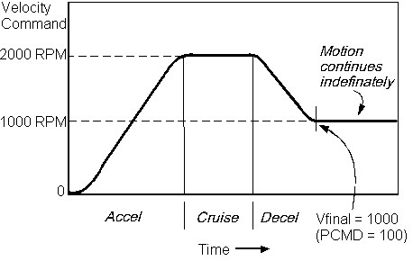
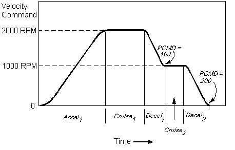
Normally, the ending speed of MOVE defaults to zero. However, you can specify an end speed other than zero (Non-Zero End Moves). To do this, use <''axis''>.VELOCITYFINAL. VELOCITYFINAL must be specified on the same line as MOVE. For example,
A1.VelocityCruise = 2000
Move A1 100 VelocityFinal = 1000
or
Move A1 100 VelocityCruise = 2000 VelocityFinal = 1000
both produce the next profile.
You seldom want to use a single move with a non-zero final velocity because motion continues until the specified ending position and abruptly begins decelerating to zero. The final position is not specified. Normally, moves with non-zero final velocities are used to build multi-step profiles.
Combining non-zero end-point moves in the motion buffer produces multi-step moves. For example:
Program
Attach A1
Call AxisSetup
Call SercosSetup
Sys.En = On
A1.En = On
Sys.Motion = On
A1.Motion = On
A1.Abs = Off
A1.StartType = Gcom
‘Do Two-step Move
Move A1 100 VCruise = 20 VFinal = 10
Move A1 100 VCruise = 10 VFinal = 0
‘Wait for move to complete and axis to settle out
While A1.IsSettled = 0
Sleep 10‘Sleep in loop to keep from overloading CPU resources
End While
‘Disable, detach and exit
A1.En = Off
Detach A1
End Program
produces the following profile.
In the above example, A1.STARTTYPE = GCOM. The second move begins when the first move is generated. You must use STARTTYPE = GCOM when chaining a non-zero end-point move to another move. You cannot use STARTTYPE = IMMED or SIMM because the new move immediately overwrites the old move. You cannot use STARTTYPE = INPOS because you want the second part of the profile to begin immediately after the first. The delay from waiting for INPOS adds error if the second move is incremental. For any move type, the move may be delayed indefinitely because moving motors never come in position unless the system is specifically tuned to do that.
You can combine non-zero end point moves to produce profiles with as many steps as you need. However, there are a few restrictions:
- STARTTYPE for all non-zero end-point moves (VELOCITYFINAL<>0) must be GCOM.
- VELOCITYCRUISE and VELOCITYFINAL are always positive. The direction is set by target position.
- PFINAL of the succeeding move must be far enough in front of PFINAL of the current move that the profile is possible with the acceleration limits. The generated profile always reaches the target position. If the acceleration and smooth limitations prevent attaining the required final velocity, the motion is terminated with the final velocity as close as possible to the required value.
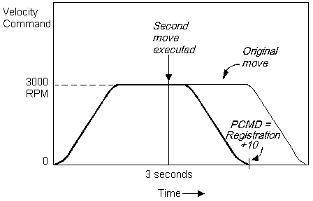
You can change the end position or velocity of a move that is in progress. You do this by setting STARTTYPE = IMMED and issuing the second move. For example, if you want to issue a move, wait a few seconds, change the end position without changing the velocity. For this, you would write:
CutAxis.StartType = Immed
CutAxis.Absolute = On
Move CutAxis 150
Sleep 3000
Move CutAxis 100
This generates the profile shown below.
As a second example, if you wanted to change the cruise velocity without changing the end-position, you would write:
CutAxis.StartType = IMMED
Move CutAxis 150
Sleep 3000
Move CutAxis 150 VCruise = 1500
You can change the final position, cruise velocity, and final velocity of any move that is executing. However, you must observe a few rules:
- STARTTYPE must be IMMED or SIMM
- Direction is set according to the target position. For Jog, according to the sign of the velocity.
- New and old VELOCITYCRUISE and VELOCITYFINAL must be positive in case of move command.
- If the succeeding move changes PFINAL or VFINAL, it must remain possible to create the profile with the axis acceleration limits
Synchronizing Multiple Axes
The softMC is abile to synchronize many single-axis MOVEs so they all start simultaneously. This is useful when you have multiple axes with moves that are largely independent, but must start at the same time. It is also useful for coordinating more than three axes. Group motion, which is covered later, provides tighter coordination, but with one movement profile.
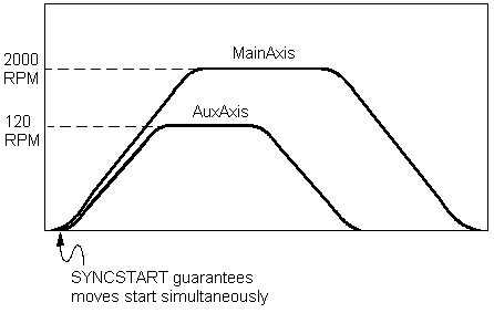
Synchronization is controlled with STARTTYPE = SYNCSTART (SYNC). The feature works by allowing you to load the motion generator with a motion command, but delaying the generation of motion until a SYNCSTART command is issued. For example, the following sequence:
Move MainAxis 300 VCruise = 1200 StartType = Sync

Sleep 1000 ‘Program delayed between Move Commands

Move AuxAxis 100 VCruise = 1000 StartType = Sync

SyncStart MainAxis AuxAxis
generates the following profiles.
You can synchronize as many axes as you want, including simulated axes. Since each SYNCSTART specifies the axes it synchronizes, you can synchronize multiple sets of axes independently.
This command incurs a minimum system delay of 2 SERCOS cycle times, but the delay may be greater, depending on the number of moves synchronized together and the total load of the system.
If you have loaded a synchronized move into the motion generator and need to delete it, use SYNCCLEAR. For example, if you entered the following command before issuing SYNCSTART:
SyncClear MainAxis
the MainAxis move is deleted. This only affects subsequent moves. You can only use SYNCCLEAR to clear pending moves. SYNCCLEAR has no effect once the move is executing. Stopping the axis in this case is performed as for a non-synchronized move.
You can override the following axis properties as part of a MOVE:
ABSOLUTE
ACCELERATION
DECELERATION
SMOOTHFACTOR
VELOCITYCRUISE
VELOCITYMAX
STARTTYPE
VELOCITYRATE
ACCELERATIONRATE
DECELERATIONRATE
JERKRATE
Velocity Override
The softMC can speed up or slow down all motion commands. This can be applied to the entire machine at once, or to individual axes, independently. This capability is used extensively in machine development as it enables you to adjust the entire machine speed in a single command. Since the command can be issued from the terminal, you can observe the operation of the machine at a variety of speeds without modifying your program.
All axes on an softMC are controlled with SYSTEM.VELOCITYOVERRIDE (SYSTEM.VORD). For example:
System.VelocityOverride = 25
immediately reduces the velocity commands of all currently executing MOVEs and JOGs and any subsequent commands to 25% of the current values. Since the velocities are controlled by VORD, the acceleration rates of all axes are proportionally adjusted. The final positions of MOVEs are not affected.
If you want to override the velocity of a single axis rather than the entire machine, you can use <''axis''>.VORD.VELOCITYOVERRIDE (<''axis''>.VORD). It is used in the same way as SYSTEM.VORD except it applies only to one axis. <''axis''>.VORD can be applied to as many or as few axes as desired and the amount of override specified for one axis is independent of the others. If you use SYSTEM.VORD and <''axis''>.VORD simultaneously, the axis speed is reduced by the product of both override properties as shown below:
System.VOrd = 66 ‘Reduce entire system to 2/3 speed

MainAxis.VOrd = 50 ‘Reduce MainAxis to 1/3 speed
In this example, the entire system is reduced to 66% and the MainAxis is reduced to 50% of the system speed which is 33%. There is a delay of 5 samples until the velocity start to change that to insure a smoothness velocity exchange.
Motion Examples
This section provides a few examples that apply the motion control techniques discussed in this chapter to common machine functions.
Homing
Most machine-axes need to establish a soft home reference position. This user-specified homing program is generally run with the power-up cycle of the machine or with a manual-mode. The soft home reference position (0000….) is established by a homing program for the hard-home plus any marker-pulse (for the integrity between the controller and axis-mechanics) with HOMEOFFSET (the distance from the hard home).
The hard-home position on a direct drive axis is usually assigned by the once-per-revolution marker pulse of the encoder (incremental, sine encoder or ENDAT encoder) or the zero-crossing position of a resolver. However, for the machine-axis with a gear-ratio (geared, belted, or ball screw, etc.), a more complicated procedure is required for the relationship (integrity) between the controller and axis-mechanics of the homing program. In these cases, it is common to place a micro-switch or proximity-switch on the axis for the indication of the hard-home-reference position.
| NOTE | |
| This home-position switch is placed on one end of the axis (inside the mechanical end of the travel-limits of the axis) with the switch tripping mechanism designed such that switch-circuit is closed on one side of the hard home-position and open on the other side of the hard home-position. |
The switch-circuit (high/low) provides the controller-input information for the direction of the home position.) Other machine axes may use absolute-position-device designs, so the integrity between the controller and axis mechanics is established automatically on the power-up of the machine . The machine position-integrity is established similarly to an axis that only rotates 360°.
The homing process itself is done by the drive and the softMC is just initiating it. All home parameters and commands are defined by the drive command set and can differ depending on the used motion bus. For EtherCAT please see also:
Registration
Registration applications are those that start motion and then modify the profile, based on a subsequent event. These applications generally involve discrete product processing, such as are common in the packaging, printing and converting industries. The event is usually generated by sensing a position on the product being processed (usually a mark is printed on the product and detected by an optical sensor). The mark is normally referred to as a registration mark.
A common registration application is cutting a product package, such as a bag or label from a web (reel). The web is printed with many copies of the product package. The controller begins to unwind the product package from the web. During this motion, the controller waits for a registration mark to be detected. After the mark is detected, the profile is modified, based on the position at which the mark was detected. Commonly, the profile comes to rest a fixed distance after the mark position where the package can be cut. There are numerous variations of this type of application. The key element is that the end position of the move cannot be calculated until after the move starts. This requires that the profile be started and then modified on-the-fly.
The softMC combines the ability to change the position end points on-the-fly and the ability to command the drive to capture a position. Registration is similar to homing except that in homing you go back to the mark, but in registration you go forward to a fixed distance after the mark. The following example shows a typical registration example:
Program
'Prepare drive to captureVCruise = 3000
Cycle:Move FeedAxis 50 'wait for captureMove FeedAxis [capture position] + 10 StartType=IMMED
End Program
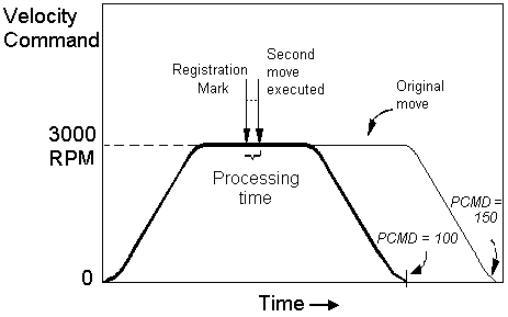
This example generates the next profile.
The move starts and the registration mark is detected about 40% of the way to the end. After a small amount of processing time, the second move is loaded over the current move. The axis comes to rest at a fixed offset after the registration mark.
The more accurately the position is determined, the more accurate the cut is with respect to the registration mark. If the process is feeding material at 10 ft/s, and the capture accuracy is ±3 microseconds, the mark is:
10 (ft/sec) * 3 µs = 3.225e-5 ft or about 0.0004 in.
The original line was set to go much farther than the actual resultant move. This technique is commonly used because you can monitor the end position and, if the move is completed before the registration mark is detected, it indicates the mark was missed.
Gating
Many applications require motion to be gated to an external switch. In these cases, you need to start a move after the gating input transitions with as little delay as possible. One way you can accomplish this on the softMC is by starting the move with events containing synchronized motion. For example:
Program
Attach MainAxis
Move MainAxis 100 Absolute=FALSE StartType=SYNC
While System.Din.1=False; ‘Wait for input to change
 Sleep 1
End While
SyncStart MainAxis ‘Start the axis up by disable
End Program
This program moves MainAxis 100 units when DIN.1 transitions high. Motion on MainAxis starts as soon after the transition of DIN.1 as possible. OnEvent can also be used.
Clamping
Clamping applications typically process discrete parts but the end point of a move is unknown. Clamping is often applied when the length of the part is not accurately known or when the thickness of material is unknown. In clamping, the controller moves an axis at low torque until the end of the material is detected. Then the torque level is increased, either to measure the part more accurately or to hold the part for another axis to process.
The softMC allows you to change torque limits on the drive and uses events to monitor position error to sense the end of the piece (below).
Program
Dim Shared PartFoundFlag As Long
OnEvent PartFound Abs(ClampingAxis.pe ) > 0.25
Stop ClampingAxis
[Set torque for heavy torque]
Sleep 30 ‘allow 30 ms for settling
PartFoundFlag=TRUE
Return
End OnEvent
eventon PartFound
[set torque for light torque]
PartFoundFlag=FALSE
Move ClampingAxis Vcruise=10
While (PartFoundFlag=FALSE)
Sleep 10End While
REM Process part here
Return
End Program
This program works by starting a slow move with low torque. The move continues until position error is greater than 0.25 units. When the axis runs into a stop, position error accumulates because the profile continues. You must be careful to set the threshold of the event greater than the position error of normal operation. The threshold of the event must also be smaller than the drive's maximum following error to avoid drive error before the event is triggered. Disable OnEvent during the acceleration of the move to avoid nuisance PartFound events.


