Difference between revisions of "TARM robot"
(→Robot Configuration) |
(Added to Category:Robot Models) |
||
| (4 intermediate revisions by 2 users not shown) | |||
| Line 1: | Line 1: | ||
| + | {{Languages|TARM_robot}} | ||
= TARM (Traverse Arm) robot = | = TARM (Traverse Arm) robot = | ||
| − | |||
| − | |||
| − | |||
| − | |||
| − | |||
| − | |||
| − | + | == General setup == | |
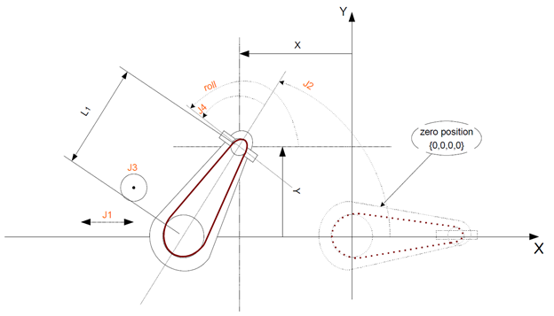
| − | + | *J1 is the linear traverse axis | |
| + | *J2 is angular axis of the Z-Roll couple. | ||
| + | *J3 linear (Z) axis of the Z-Roll couple. | ||
| + | *J4 additional rotational axis of the end-effector. | ||
| − | == | + | == Kinematics == |
| − | + | [[File:Inverse dynamic model for Traverse Arm kinematics - Definitions.png|RTENOTITLE]] | |
| + | == Main Kinematics Equations == | ||
| + | === Direct Kinematics: === | ||
| + | |||
| + | === Inverse Kinematics: === | ||
{{Note|Singularity J2 at 90 degrees!}} | {{Note|Singularity J2 at 90 degrees!}} | ||
| − | Additionally there is standard coupling between motor axes A2, A3 and J2, J3 (the | + | Additionally there is standard coupling between motor axes A2, A3 and J2, J3 (the SCARA/OCP gear box). |
| − | SCARA/OCP gear box). | + | |
| + | | ||
| + | == Robot Configuration == | ||
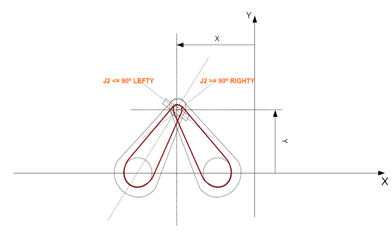
| − | + | [[File:TARMCONFIG.PNG|800px|TARMCONFIG.PNG]] | |
| − | + | | |
| + | == Reference positions == | ||
| − | |||
Cartesian Location Joint (LEFTY) Joint (Righty) | Cartesian Location Joint (LEFTY) Joint (Righty) | ||
| − | #{L1 , 0 , 0 , 0} {0 , 0 , 0 , 0} {2L1 , 180 , 0 , -180} | + | |
| − | #{0 , L1 , 0 , 0}1 {0 , 90 , 0 , -90} {0 , 90 , 0 , -90} | + | #{L1 , 0 , 0 , 0} {0 , 0 , 0 , 0} {2L1 , 180 , 0 , -180} |
| − | #{-L1 , 0 , 0 , 0} {-2*L1 , 0 , 0 , 0} {0 , 180 , 0 , -180} | + | #{0 , L1 , 0 , 0}1 {0 , 90 , 0 , -90} {0 , 90 , 0 , -90} |
| − | #{0 , 0 , 0 , 0} {-L1 , 0 , 0 , 0} {L1 , 180 , 0 , -180} | + | #{-L1 , 0 , 0 , 0} {-2*L1 , 0 , 0 , 0} {0 , 180 , 0 , -180} |
| − | + | #{0 , 0 , 0 , 0} {-L1 , 0 , 0 , 0} {L1 , 180 , 0 , -180} | |
| − | + | ||
| − | + | | |
| − | Setup file | + | |
| − | This kinematics type is defined using “model = 7” identifier | + | == Setup file == |
| − | Traverse Arm Kinematics group definition | + | |
| − | common shared Tarm as group axnm = a5 axnm = a6 axnm = a7 axnm = a8 model = 7 | + | This kinematics type is defined using “model = 7” identifier. Traverse Arm Kinematics group definition: |
| − | The only geometric parameter – segment length L1 is kept in <robot>.link[1][1] | + | |
| − | Standard | + | common shared Tarm as group axnm = a5 axnm = a6 axnm = a7 axnm = a8 model = 7 |
| − | Z-Roll | + | |
| − | coupling | + | The only geometric parameter – segment length L1 is kept in '''<robot>.link[1][1]''' |
| − | definition | + | |
| − | (same as | + | {| border="1" width="20%" |
| − | SCARA or | + | |- |
| − | OCP) | + | ! width="50" | |
| − | cplg[1][1] = 1 | + | ! width="50" | |
| − | cplg[1][2] = 0 | + | |- |
| − | cplg[1][3] = 0 | + | | |
| − | cplg[1][4] = 0 | + | Standard Z-Roll coupling definition (same as SCARA or OCP) |
| − | cplg[2][1] = 0 | + | |
| − | cplg[2][2] = 1 | + | | |
| − | cplg[2][3] = 0 | + | cplg[1][1] = 1<br/> cplg[1][2] = 0<br/> cplg[1][3] = 0<br/> cplg[1][4] = 0<br/> cplg[2][1] = 0<br/> cplg[2][2] = 1<br/> cplg[2][3] = 0<br/> cplg[2][4] = 0<br/> cplg[3][1] = 0<br/> cplg[3][2] = 0<br/> cplg[3][3] = 1<br/> cplg[3][4] = 40/360 ' 40mm/per revolution<br/> cplg[4][1] = 0<br/> cplg[4][2] = 0<br/> cplg[4][3] = 0<br/> cplg[4][4] = 1<br/> coupled = 1 |
| − | cplg[2][4] = 0 | + | |
| − | cplg[3][1] = 0 | + | |- |
| − | cplg[3][2] = 0 | + | | |
| − | cplg[3][3] = 1 | + | Definition of L1 = 500 mm and positive vertical direction of Z axis. |
| − | cplg[3][4] = 40/360 ' 40mm/per revolution | + | |
| − | cplg[4][1] = 0 | + | | |
| − | cplg[4][2] = 0 | + | axis[1][1] = 0<br/> axis[1][2] = 0<br/> axis[1][3] = 1<br/> link[1][1] = 500<br/> link[1][2] = 0<br/> link[1][3] = 0 |
| − | cplg[4][3] = 0 | + | |
| − | cplg[4][4] = 1 | + | |} |
| − | coupled = 1 | + | |
| − | Definition of L1 = 500 mm and positive | + | [[Category:Robot Models]] |
| − | vertical direction of Z axis. | ||
| − | axis[1][1] = 0 | ||
| − | axis[1][2] = 0 | ||
| − | axis[1][3] = 1 | ||
| − | link[1][1] = 500 | ||
| − | link[1][2] = 0 | ||
| − | link[1][3] = 0 | ||
| − | |||
Latest revision as of 05:35, 8 April 2022
| Language: | English • 中文(简体) |
|---|
Contents
TARM (Traverse Arm) robot
General setup
- J1 is the linear traverse axis
- J2 is angular axis of the Z-Roll couple.
- J3 linear (Z) axis of the Z-Roll couple.
- J4 additional rotational axis of the end-effector.
Kinematics
Main Kinematics Equations
Direct Kinematics:
Inverse Kinematics:
| NOTE | |
| Singularity J2 at 90 degrees! |
Additionally there is standard coupling between motor axes A2, A3 and J2, J3 (the SCARA/OCP gear box).
Robot Configuration
Reference positions
Cartesian Location Joint (LEFTY) Joint (Righty)
#{L1 , 0 , 0 , 0} {0 , 0 , 0 , 0} {2L1 , 180 , 0 , -180}
#{0 , L1 , 0 , 0}1 {0 , 90 , 0 , -90} {0 , 90 , 0 , -90}
#{-L1 , 0 , 0 , 0} {-2*L1 , 0 , 0 , 0} {0 , 180 , 0 , -180}
#{0 , 0 , 0 , 0} {-L1 , 0 , 0 , 0} {L1 , 180 , 0 , -180}
Setup file
This kinematics type is defined using “model = 7” identifier. Traverse Arm Kinematics group definition:
common shared Tarm as group axnm = a5 axnm = a6 axnm = a7 axnm = a8 model = 7
The only geometric parameter – segment length L1 is kept in <robot>.link[1][1]
|
Standard Z-Roll coupling definition (same as SCARA or OCP) |
cplg[1][1] = 1 |
|
Definition of L1 = 500 mm and positive vertical direction of Z axis. |
axis[1][1] = 0 |

