Difference between revisions of "AXY:Operational Modes"
(AXY: new links) |
|||
| (3 intermediate revisions by 2 users not shown) | |||
| Line 179: | Line 179: | ||
== Entering the digital torque mode == | == Entering the digital torque mode == | ||
=== From digital position to digital torque === | === From digital position to digital torque === | ||
| − | According to the current MC rules for the movement commands. The | + | According to the current MC rules for the movement commands. The trapezoidal velocity profiler is used. The current ''torque feedback'' will be taken for the initial torque value. The picture shows the time-position/velocity/torque graphs of the command execution: |
DigitalTorque trq ''StartType=Immediate'' | DigitalTorque trq ''StartType=Immediate'' | ||
| Line 192: | Line 192: | ||
=== From digital velocity to digital torque === | === From digital velocity to digital torque === | ||
| − | According to the current MC rules for the movement commands. The | + | According to the current MC rules for the movement commands. The trapezoidal velocity profiler is used. The current ''torque feedback'' will be taken for the initial torque value. The picture shows the time-velocity/torque graphs of the command execution: |
DigitalTorque trq ''StartType=Immediate'' | DigitalTorque trq ''StartType=Immediate'' | ||
| Line 206: | Line 206: | ||
=== From analog velocity to digital torque === | === From analog velocity to digital torque === | ||
| − | According to the current MC rules for the movement commands. The | + | According to the current MC rules for the movement commands. The trapezoidal velocity profiler is used. The current ''torque feedback'' will be taken for the initial torque value. The picture shows the time-velocity/torque graphs of the command execution: |
DigitalTorque trq ''StartType=Immediate'' | DigitalTorque trq ''StartType=Immediate'' | ||
| Line 217: | Line 217: | ||
=== From analog torque to digital torque === | === From analog torque to digital torque === | ||
| − | According to the current MC rules for the movement commands. The | + | According to the current MC rules for the movement commands. The trapezoidal velocity profiler is used. The current ''torque feedback'' will be taken for the initial torque value. The picture shows the time-velocity/torque graphs of the command execution: |
DigitalTorque trq ''StartType=Immediate'' | DigitalTorque trq ''StartType=Immediate'' | ||
| Line 258: | Line 258: | ||
* When entering the digital position mode the usual stopping profile will be generated using the modal DecMax value. | * When entering the digital position mode the usual stopping profile will be generated using the modal DecMax value. | ||
* When entering the digital velocity mode the usual stopping profile will be generated using the modal DecMax value. | * When entering the digital velocity mode the usual stopping profile will be generated using the modal DecMax value. | ||
| − | * <nowiki>When entering the digital torque mode the system generates a | + | * <nowiki>When entering the digital torque mode the system generates a trapezoidal profile reducing the command torque to zero during the modal <TimeToTorque> milli-seconds.</nowiki> |
==== From analog velocity to digital position ==== | ==== From analog velocity to digital position ==== | ||
| Line 316: | Line 316: | ||
= Properties and Commands = | = Properties and Commands = | ||
| − | * [[MC-Basic: | + | * [[MC-Basic:element.TORQUECOMMAND|TORQUECOMMAND]] |
| − | * [[MC-Basic: | + | * [[MC-Basic:element.TORQUEFEEDBACK|TORQUEFEEDBACK]] |
| − | * [[ | + | * [[MC-Basic:element.WOMODE|WOMODE]] |
| − | * [[ | + | * [[MC-Basic:element.ANALOGTORQUESCALE|ANALOGTORQUESCALE]] |
| − | * [[ | + | * [[MC-Basic:element.ANALOGVELOCITYSCALE|ANALOGVELOCITYSCALE]] |
| − | * [[ | + | * [[MC-Basic:element.TIMETOTORQUE|TIMETOTORQUE]] |
| − | * [[ | + | * [[MC-Basic:element.TIMETORQUE|TIMETORQUE]] |
| − | * [[ | + | * [[MC-Basic:element.DIGITALTORQUE|DIGITALTORQUE]] |
Latest revision as of 12:49, 13 September 2017
| IMPORTANT | |
| This entry is outdated and requires revision. |
Contents
- 1 Introduction
- 2 Operation modes
- 3 Setting a mode (transition between the modes)
- 3.1 Entering position mode
- 3.2 Entering the digital velocity mode
- 3.3 Entering the digital torque mode
- 3.4 Entering the analog velocity mode
- 3.5 Entering the analog torque mode
- 3.6 The explicit mode change (WoMode - command)
- 3.6.1 Entering digital modes
- 3.6.1.1 From analog velocity to digital position
- 3.6.1.2 From analog torque to digital position 2
- 3.6.1.3 From digital velocity to digital position 2
- 3.6.1.4 From digital torque to digital position2
- 3.6.1.5 From analog velocity to digital velocity 2
- 3.6.1.6 From analog torque to digital velocity
- 3.6.1.7 From digital position to digital velocity 2
- 3.6.1.8 From digital torque to digital velocity 2
- 3.6.1.9 From analog velocity to digital torque
- 3.6.1.10 From analog torque to digital torque 2
- 3.6.1.11 From digital position to digital torque 2
- 3.6.1.12 From digital velocity to digital torque
- 3.6.1 Entering digital modes
- 4 Properties and Commands
- 5 Side effects
- 6 Appendix (future features)
Introduction
Purpose of the document
This document describes the softMC operational modes. Interaction of other commands and transition between modes are described. General software architecture and command syntax is presented.
Operation Modes
The softMC supports 3 modes of operation:
- Digital position
- Digital velocity
- Digital torque
Independently of the current operation mode, in each motion sampling period the softMC always sends the following data to the drive:
- position - PCMD
- velocity - VCMD
- torque - TCMD (???)
Depending on the current drive operation mode only the relevant values will be taken. The drive always (each communication sample) sends the following data back to the softMC:
- feedback position(PFB)
- feedback torque(TFB)
Changing the modes is done implicitly by issuing MOVE (position), JOG (position) or TORQUE (torque) commands, or explicitly by the WoMode command.
The three drive modes will be pre-defined using the IDN’s 32-34. Selecting new drive mode is done in the following way:
- The motion RTK task sends a control-word to the drive each communication cycle. In that control word the bits 7-8 define the drive mode. This bits are changed and the control word is sent to the drive.
- When the drive successfully finishes the mode change, it returns the new mode in the status word, that is sent periodically from the drive to the softMC.
The transition between modes will be calculated in the drive’s background loop and will take:
- x communication samples for transitions from Position/Velocity to Torque
- y communications samples for transitions from Torque to Position/Velocity
where x and y depend from the drive's manufacturer.
Program Example
Program
  attach Ax1
     WoMode Ax1 Vmode
     Move Ax1 1000
     sleep 5000
     Torque Ax1 500
  detach Ax1
End Program
Operation modes
In all transitions the command for changing the new drive mode is entered from the RTK at the sample of the motion package exchange. After one of the mode-change commands(see below) is executed and completed the system keeps that mode until the next change is issued.
Position Mode
- The default softMC mode.
- Entered by issuing a MOVE or WoMode Pmode command.
- The drive takes position and velocity command (PCMD, VCMD) each softMC motion sample.
Velocity Mode
- Entered by issuing WoMode Vmode command.
- The drive takes velocity command (VCMD) each softMC motion sample.
- The velocity is generated by the profiler in the same way as in digital position mode
Torque Mode
- Entered by issuing a DIGITALTORQUE or WoMode DTmode command.
- The drive takes torque command (TCMD) each softMC motion sample.
- The command torque value is computed changing the value linearly from the initial torque value to the target torque value during the given time TimeToTorque.
Setting a mode (transition between the modes)
Entering position mode
From velocity mode to position mode
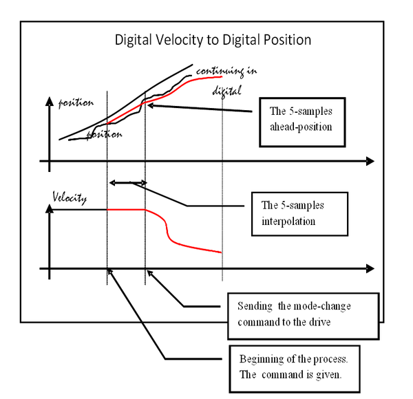
According to the current softMC rules for the movement commands. If the StartType is Immediate the new movement will be exchanged on-the-fly taking the current position feedback and the current velocity & acceleration command for the 5-samples position prediction, therefore small position jumps can occur - this due to the inability to compute exactly the 5-samples ahead-position. The picture shows the time-position/velocity graphs of the command execution:
MOVE pos StartType=Immediate
entered while the system was in DIGITAL-VELOCITY mode. If the StartType is Super-Immediate then, the initial position will be set to the current position feedback. In this case, no position jump can occur.
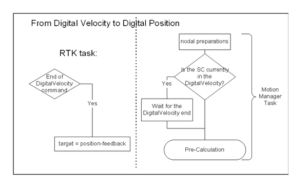
If the movement is not an immediate one, the Motion Manager Task will wait until the current digital torque command finishes. Only when the torque is zero, the current feedback position will be taken for the start position of the next movement pre-calculation. Again, due to the uncertain movements in the torque mode there could be some position jumps. (See 5.11)
Under the assumption that transition from velocity to position mode in the drive doesn’t take more then 1-2 motion samples, there shouldn’t be any visible disturbances during the transition. Also, during the drive mode transition, the velocity & position commands are changed smoothly and sent both to the drive during whole transition process.
From digital torque to digital position
According to the current MC rules for the movement commands.
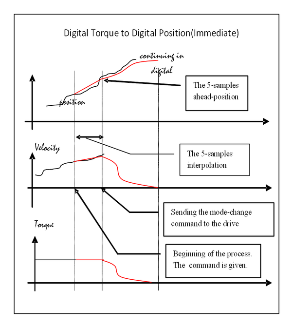
If the StartType is Immediate the new movement will be exchanged on-the-fly taking the current position, velocity and acceleration feedback for the 5-samples position prediction, therefore small jumps in position can occur - this due to the inability to compute exactly the 5-samples ahead-position. The picture shows the time-position/velocity/torque graphs of the command execution:
MOVE pos StartType=Immediate
entered while the system was in DIGITAL-TORQUE mode. If the StartType is Super-Immediate then, the initial position & velocity will be set to the current position & velocity feedback. In this case, no position jump can occur.
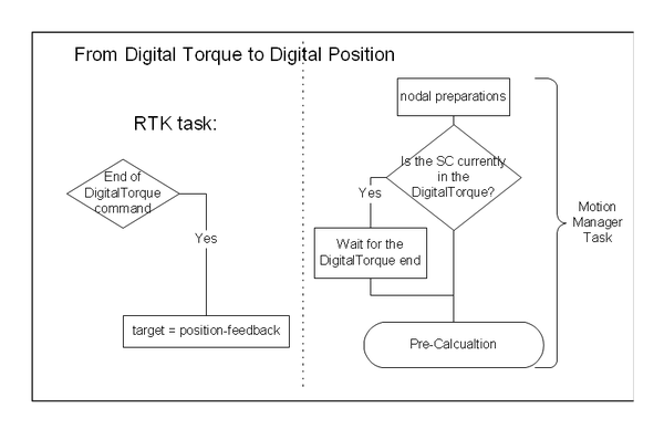
If the movement is not an immediate one, the Motion Manager Task will wait until the current digital torque command finishes. Only when the torque is zero, the current feedback position will be taken for the start position of the next movement pre-calculation. Again, due to the uncertain movements in the torque mode there could be some position jumps. (See 5.11)
Under the assumption that transition from torque to position mode in the drive doesn’t take more then 2-3 motion samples, there shouldn’t be any visible disturbances. Also, during the transition between the drive modes the torque command is kept constant, while the position & velocity are smoothly changed according to the used profiler. Only when the drive mode transition is completed the system enters the torque-following mode and the TCMD follows the TFB value. (See: 5.7 Following modes).
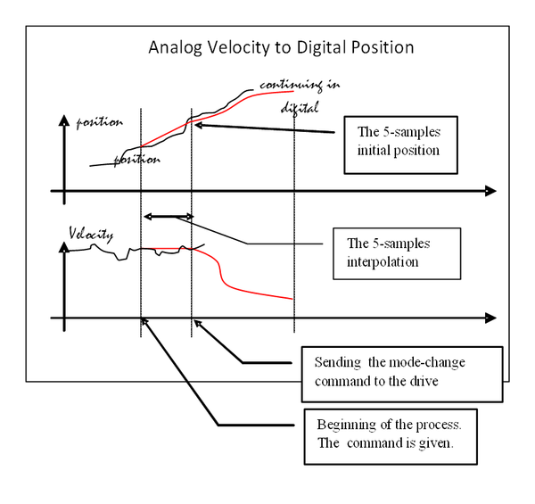
From analog velocity to digital position
Only the MOVE commands with StartType=Immediate/Super-Immediate will be accepted, other StartType values will cause an error. A 5-samples constant acceleration prediction based on the feedback position & acceleration and the command velocity will be used for calculating the initial position. Therefore small jumps in position can occur - this due to the inability to compute exactly the 5-samples ahead-position. The picture shows the time-position/velocity graphs of the command execution:
MOVE pos StartType=Immediate
entered while the system was in ANALOG-VELOCTY mode. If the StartType is Super-Immediate then, the initial position & velocity will be set to the current position & velocity feedback. In this case, no position jump can occur.
Under the assumption that transition from velocity to position mode in the drive doesn’t take more then 1-2 motion samples, there shouldn’t be any visible disturbances during the transition. Also, during the drive mode transition the velocity & position commands are changed smoothly and sent both to the drive during whole transition process.
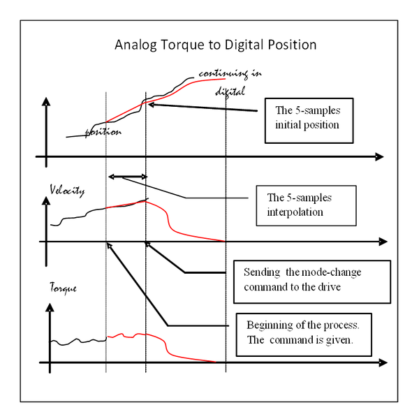
From analog torque to digital position
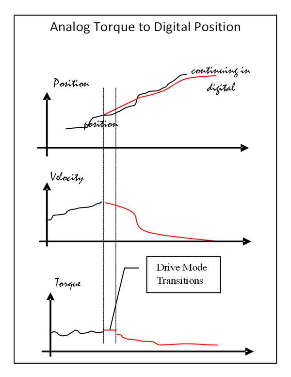
Only the MOVE commands with StartType=Immediate/Super-Immediate will be accepted, other StartType values will cause an error. A 5-samples constant acceleration prediction based on the feedback position, velocity & acceleration, will be used for calculating the initial position. Therefore small jumps in position can occur - this due to the inability to compute exactly the 5-samples ahead-position. The picture shows the time-position/velocity/torque graphs of the command execution:
MOVE pos StartType=Immediate
entered while the system was in ANALOG-VELOCTY mode. If the StartType is Super-Immediate then, the initial position & velocity will be set to the current position & velocity feedback. In this case, no position jump can occur.
Under the assumption that transition from torque to position mode in the drive doesn’t take more then 2-3 motion samples, there shouldn’t be any visible disturbances. Also, during the transition between the drive modes the torque command is kept constant, while the position & velocity are smoothly changed according to the used profiler. Only when the drive mode transition is completed the system enters the torque-following mode and the TCMD follows the TFB value. (See: 5.7 Following modes).
Entering the digital velocity mode
From digital position to digital velocity
The motion is continued by entering new movement according to its StartType (Immediate, Super-Immediate, Generator-Completed, In-position), same as in MC. Both modes are profiler-driven, due to the fact that the implementation of digital-velocity mode does not differ from the digital-position mode, except the operation inside drive, the transitions are exactly the same as transitions between MOVE and JOG commands in MC.
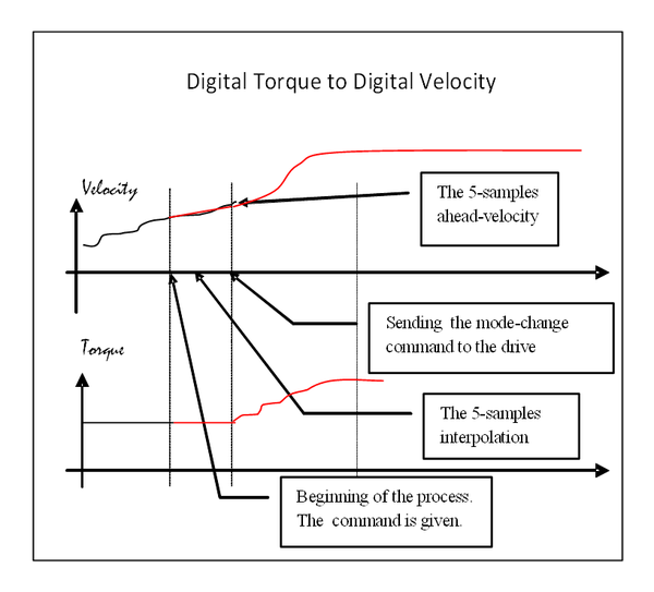
From digital torque to digital velocity
According to the current MC rules for the movement commands. If the StartType is Immediate the new movement will be exchanged on-the-fly taking the current velocity & acceleration feedback for calculating the 5-samples ahead velocity value of the next movement, executed in velocity mode. Therefore, small jumps in position can occur - this due to the inability to compute exactly the 5-samples ahead-position. The picture shows the time-velocity/torque graphs of the command execution:
JOG vel StartType=Immediate
entered while the system was in DIGITAL-TORQUE mode. If the StartType is Super-Immediate then, the initial position & velocity will be set to the current position & velocity feedback. In this case, no position jump can occur.
If the movement is not an immediate one, the user-task will wait until the current digital torque command finishes. Only when the torque is zero, the current feedback velocity will be taken for the initial velocity of the next movement pre-calculation. Again, due to the uncertain movements in the torque mode there could be some position jumps.
Under the assumption that transition from torque to velocity mode in the drive doesn’t take more then 2-3 motion samples, there shouldn’t be any visible disturbances. Also, during the transition between the drive modes the torque command is kept constant, while the position & velocity are smoothly changed according to the used profiler. Only when the drive mode transition is completed the system enters the torque-following mode and the TCMD follows the TFB value. (See: 5.7 Following modes).
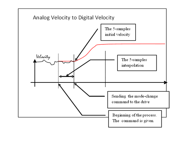
From analog velocity to digital velocity
Only the JOG commands with StartType=Immediate/Super-Immediate will be accepted, other StartType values will cause an error. A 5-samples constant acceleration prediction based on the feedback position & acceleration and the command velocity will be used for calculating the initial position. Therefore small jumps in position can occur - this due to the inability to compute exactly the 5-samples ahead-position. The picture shows the time-velocity graphs of the command execution:
JOG vel StartType=Immediate
entered while the system was in ANALOG-VELOCTY mode. If the StartType is Super-Immediate then, the initial position & velocity will be set to the current position & velocity feedback. In this case, no position jump can occur.
In this case the drive does not change the mode, therefore no transition problems can occur.
From analog torque to digital velocity
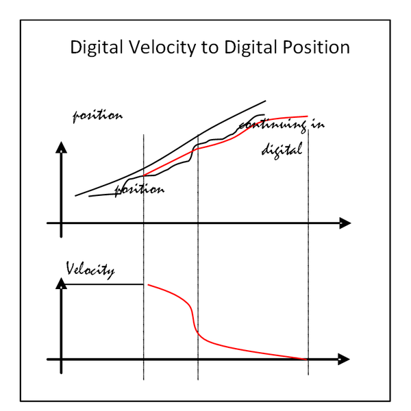
Only the JOG commands with StartType=Immediate/Super-Immediate will be accepted, other StartType values will cause an error. A 5-samples constant acceleration prediction based on the feedback position, velocity & acceleration will be used for calculating the initial velocity. Therefore small jumps in position can occur - this due to the inability to compute exactly the 5-samples ahead-position. The picture shows the time-position/velocity graphs of the command execution:
JOG vel StartType=Immediate
entered while the system was in ANALOG-TORQUE mode. If the StartType is Super-Immediate then, the initial position & velocity will be set to the current position & velocity feedback. In this case, no position jump can occur.
Under the assumption that transition from torque to velocity mode in the drive doesn’t take more then 2-3 motion samples, there shouldn’t be any visible disturbances. Also, during the transition between the drive modes the torque command is kept constant, while the velocity is smoothly changed according to the used profiler. Only when the drive mode transition is completed the system enters the torque-following mode and the TCMD follows the TFB value. (See: 5.7 Following modes).
Entering the digital torque mode
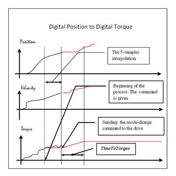
From digital position to digital torque
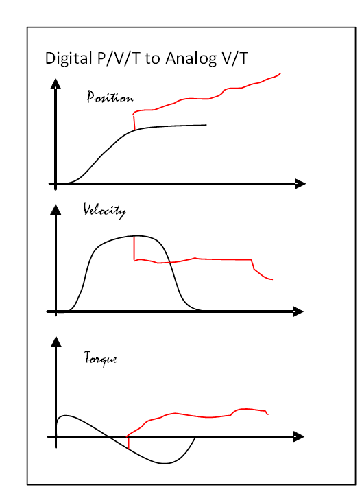
According to the current MC rules for the movement commands. The trapezoidal velocity profiler is used. The current torque feedback will be taken for the initial torque value. The picture shows the time-position/velocity/torque graphs of the command execution:
DigitalTorque trq StartType=Immediate
entered while the system was in DIGITAL-POSITION mode.
If the movement (DigitalTorque-command) is not an immediate one, the user-task will wait until the current digital position command finishes. The current feedback torque will be taken for the initial torque of the next movement pre-calculation.
Under the assumption that transition from position to torque mode in the drive doesn’t take more then 1-2 motion samples, there shouldn’t be any visible disturbances. Also, during the transition between the drive modes the torque command is changed according its profiler while the position & velocity are kept on the values of the sample when the change was ordered.
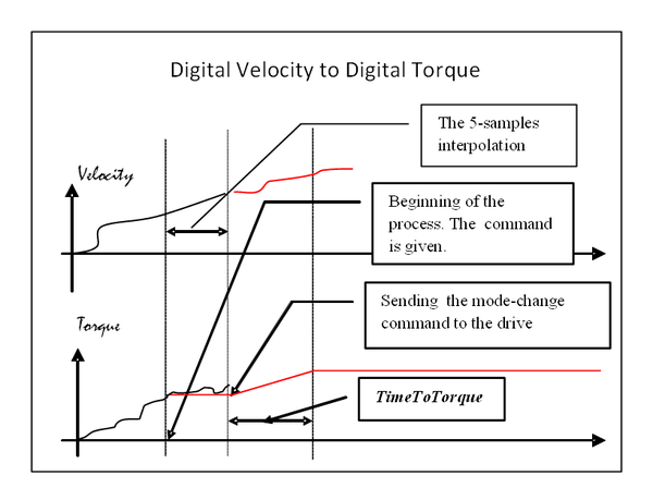
From digital velocity to digital torque
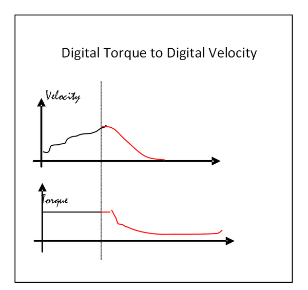
According to the current MC rules for the movement commands. The trapezoidal velocity profiler is used. The current torque feedback will be taken for the initial torque value. The picture shows the time-velocity/torque graphs of the command execution:
DigitalTorque trq StartType=Immediate
entered while the system was in DIGITAL-VELOCITY mode.
If the movement (DigitalTorque-command) is not an immediate one, the user-task will wait until the current digital position command finishes. The current feedback torque will be taken for the initial torque of the next movement pre-calculation.
Under the assumption that transition from velocity to torque mode in the drive doesn’t take more then 1-2 motion samples, there shouldn’t be any visible disturbances. Also, during the transition between the drive modes the torque command is changed according its profiler while the position & velocity are kept on the values of the sample when the change was ordered.
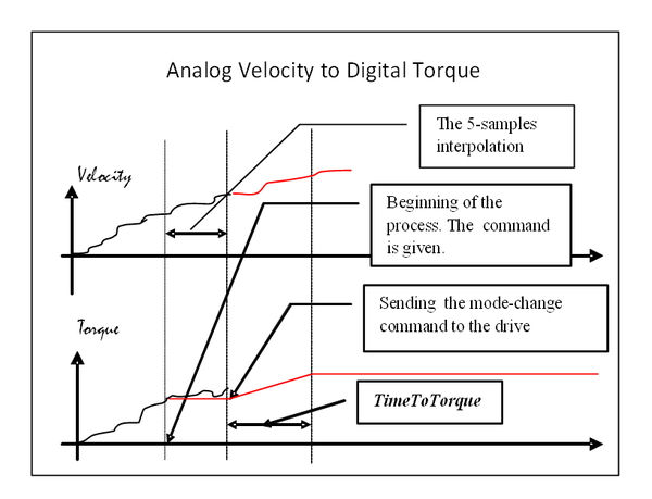
From analog velocity to digital torque
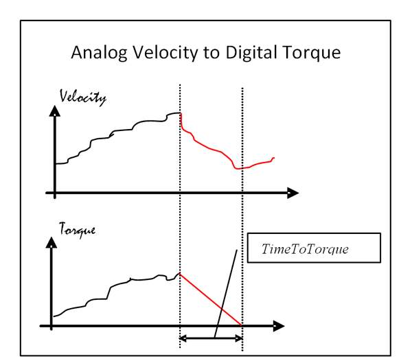
According to the current MC rules for the movement commands. The trapezoidal velocity profiler is used. The current torque feedback will be taken for the initial torque value. The picture shows the time-velocity/torque graphs of the command execution:
DigitalTorque trq StartType=Immediate
entered while the system was in ANALOG-VELOCITY mode.
Under the assumption that transition from velocity to torque mode in the drive doesn’t take more then 1-2 motion samples, there shouldn’t be any visible disturbances. Also, during the transition between the drive modes the torque command is changed according its profiler while the position & velocity are kept on the values of the sample when the change was ordered.
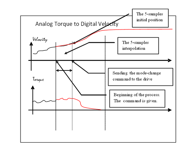
From analog torque to digital torque
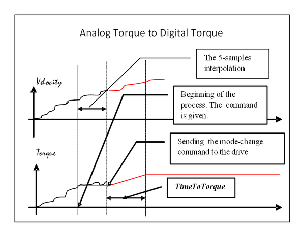
According to the current MC rules for the movement commands. The trapezoidal velocity profiler is used. The current torque feedback will be taken for the initial torque value. The picture shows the time-velocity/torque graphs of the command execution:
DigitalTorque trq StartType=Immediate
entered while the system was in ANALOG-TORQUE mode.
In this case the drive does not change the mode, therefore no transition problems can occur.
Entering the analog velocity mode
Immediate switching to analog command, no deceleration profile. The smoothness of transition is user’s responsibility. The analog velocity mode is entered by issuing command:
WoMode AVmode
If there is some motion (Move/Jog/DigitalTorque) currently executing or pending it will be canceled.
Entering the analog torque mode
Immediate switching to analog command, no deceleration profile. The smoothness of transition is user’s responsibility. The analog velocity mode is entered by issuing command:
WoMode ATmode
If there is some motion(Move/Jog/DigitalTorque) currently executing or pending it will be canceled.
The explicit mode change (WoMode - command)
Entering digital modes
Operation modes can be changed implicitly and explicitly. The implicit changes are made using the Move/Jog/DigitalTorque commands as described in previous paragraphs. The operation modes can be changed explicitly using the WoMode command. If the desired mode (mode given as an argument of the WoMode command) is one of the digital modes (position, velocity or torque) the mode change is done at the motion end, means at the generator end. In certain cases the generator end doesn’t necessary mean the – no movements.
- When the movement in digital position mode is executed it can be specified with a non-zero final velocity.
- When the command torque is zero, in the digital torque mode, the motor could be moving.
From all these reasons when explicitly entering in one of the digital modes the system will automatically execute a kind of automatic-braking procedure(stopping). Namely:
- When entering the digital position mode the usual stopping profile will be generated using the modal DecMax value.
- When entering the digital velocity mode the usual stopping profile will be generated using the modal DecMax value.
- When entering the digital torque mode the system generates a trapezoidal profile reducing the command torque to zero during the modal <TimeToTorque> milli-seconds.
From analog velocity to digital position
The current position feedback and the velocity command values will be set as initial values for the stopping profile. The initial acceleration will be set to zero. During the transition between the drive modes the velocity & position values are changed according to the profiler.
From analog torque to digital position 2
The current position and velocity feedback values will be set as initial values for the stopping profile. The initial acceleration will be set to zero. During the transition between the drive modes the torque command is changed according its source while the position & velocity are changed according to the profiler.
From digital velocity to digital position 2
The current position feedback and the velocity & acceleration command values will be set as initial values for the stopping profile.
From digital torque to digital position2
The current position and velocity feedback values will be set as initial values for the stopping profile. The initial acceleration will be set to zero. During the transition between the drive modes the torque command kept on its initial value(the value at the beginning of the process) while the position & velocity are changed according to the profiler.
From analog velocity to digital velocity 2
The current position feedback and the velocity command values will be set as initial values for the stopping profile. The initial acceleration will be set to zero. 600px
From analog torque to digital velocity
The current position and velocity feedback values will be set as initial values for the stopping profile. The initial acceleration will be set to zero. During the transition between the drive modes the torque command is changed according its source while the position & velocity are changed according to the profiler.
From digital position to digital velocity 2
The current position, velocity and acceleration command values will be set as initial values for the stopping profile. During the transition between the drive modes the velocity & position values are changed according tot he profiler. The action is identical to stopping in digital position mode. 600px
From digital torque to digital velocity 2
The current position and velocity feedback values will be set as initial values for the stopping profile. The initial acceleration will be set to zero. During the transition between the drive modes the torque command kept on its initial value(the value at the beginning of the process) while the position & velocity are changed according to the profiler.
From analog velocity to digital torque
The current torque feedback value will be changed to zero during the modal value of the TimeToTorque property. During the transition between the drive modes the position & velocity values will be kept on its initial values (the value at the beginning of the process) while the torque value is changed according to the profile.
From analog torque to digital torque 2
The current torque command value will be changed to zero during the modal value of the TimeToTorque property. During the transition between the drive modes the position & velocity values will be kept on its initial values (the value at the beginning of the process) while the torque value is changed according to the profile.
From digital position to digital torque 2
The current torque feedback value will be changed to zero during the modal value of the TimeToTorque property. During the transition between the drive modes the position & velocity values will be kept on its initial values (the value at the beginning of the process) while the torque value is changed according to the profile.
From digital velocity to digital torque
The current torque feedback value will be changed to zero during the modal value of the TimeToTorque property. During the transition between the drive modes the position & velocity values will be kept on its initial values (the value at the beginning of the process) while the torque value is changed according to the profile.
Properties and Commands
- TORQUECOMMAND
- TORQUEFEEDBACK
- WOMODE
- ANALOGTORQUESCALE
- ANALOGVELOCITYSCALE
- TIMETOTORQUE
- TIMETORQUE
- DIGITALTORQUE
Move
Command* Automatically enters DIGITAL-POSITION mode.
- If the softMC is in one of the analog modes only StartType=Immediate is allowed. Any other StartType value will cause an error.
JOG
- Command Automatically enters DIGITAL-VELOCITY mode.
- If the softMC is in one of the analog modes only StartType=Immediate is allowed. Any other StartType value will cause an error.
Constants
DPmode(0) – digital position
DVmode(1) – digital velocity
DTmode(2) – digital torque
AVmode(3) – analog velocity mode
ATmode(4) – analog torque mode
Motion properties vs. Operation Modes
See Motion properties vs. Operation Modes
Side effects
Following error detection
- The following error is checked only in the digital position mode.
Gearing/Camming
- Gearing/Camming is allowed only in digital position mode, trying to set slave property while not in digital position mode will cause an error. Also trying to change mode from digital position to some other modes while Gearing/Camming will cause an error. This is true for the mode of the slave axis only, the master axis mode can be freely defined.
isMoving
- The isMoving flag will be set to according to the executing movement command (MOVE/JOG/DTORQUE) as in MC. In analog modes it is set to –2 (-1 slave, 0/1/2/3 – move).
isSettled
- The isSettled flag will be set to according to the executing movement command (MOVE/JOG/DTORQUE) as in MC. In analog modes it is set to 0.
Attachment/Detachment
- Detach will wait the program until the end of movement, means isMoving = 0.
- The analog modes set the axis attached to the executing task (or monitor) until the mode is changed to a digital one.
- This also means that WoMode AVmode command executed from a monitor implicitly attaches the axis to the monitor and that no other task can attach/move the axis until the mode isn’t changed to a digital one.
Homing
- Homing is allowed only in digital position mode. If the user tries to execute it in other modes or tries to set other modes during the home an error will be returned.
Following Modes
- When the SC is in a position or velocity mode, the TCMD value will be equal to the TFB returned from the drive (torque following).
- When the SC is in a torque mode, the PCMD and VCMD will have the feedback values, i.e., as in position-following mode.
- When the SC is in a digital velocity mode, the PCMD is calculated by the profiler generating the velocity.
- When the SC is in analog velocity mode, the PCMD is equal to the PFB (position following).
Transition Timeout
If the drive doesn’t succeed in changing mode after a predefined number of samples a fatal-error is sent to the error-handler.
Stop/Proceed
Stop command
- Digital Position mode – the stop command works according to the same rules as in MC, generates profile according to the current modal value of DecMax.
- Digital Velocity mode – the stop command works according to the same rules as in MC, generates profile according to the current modal value of DecMax.
- Digital Torque mode – the torque is linearly reduced to zero, the time of the torque reduction is defined by the modal value of TimeToTorque property.
- Analog Velocity mode – The system changes its mode to Digital-Velocity and executes the stop command according to the same rules as in MC, generates profile according to the current modal value of DecMax. There will be no movements in the proceed buffers. The previous mode will be stored.
- Analog Velocity mode – The system changes its mode to Digital-Torque and executes the stop command according reducing the torque linearly to zero, the time of the torque reduction is defined by the modal value of TimeToTorque property. There will be no movements in the proceed buffers. The previous mode will be stored.
For all modes:
After executing the stop command the attachment behavior and the behavior of all movement commands (Move/Jog/DigitalTorque) is the same as in MC (returning error and pending commands).
Proceed command
The proceed command behaves as in the MC it releases the interpreter and re-activates the movement commands previously stored in the proceed buffers. If the operational mode before the execution of the last stop command was an analog one such mode will be re-activated. The stored modes will be not buffered. New stop command overrides the old stored modes in the same ways as the motion buffer override each other on subsequent stop commands.
The ProceedType = CLEAR(3) sets the system to its default state (DIGITAL-POSITION) mode
Blending
Blending between different modes will be disabled. If two commands of different operation modes are blended, the system will automatically disable the bled functionality without notifying the user and the motions will be executed as if they were entered with no blending option(cp=0)
Waiting for the motion end
In cases of changing the axis mode from digital velocity or torque to digital position by a MOVE command that is not immediate the system will wait for ending the current movement and then, it will execute the pre-calculation of the MOVE command. The waiting occurs in the Motion Manager which effectively prevents other movements to be processed. In case of the single-axis movement it is not a problem because there are no other movements. In case of a multi-axes system this can cause a problem. The other possibility is to make the waiting in the context of the user-task, then there is a problem when the movement is issued from the monitor where waiting is not allowed.(See 3.1.1, 3.1.2 )
Appendix (future features)
Velocity following error
Checking the difference between velocity command and velocity feedback against a given threshold (max).
Torque following error
Checking the difference between torque command and torque feedback against a given threshold (max).
Additive torque
To add torque value together with position/velocity. The drive supports such an option but the SC should run two profilers in parallel (one for the position/velocity & one for the torque)
Analog superposition
The analog inputs can be active together with the digital modes. The values are added to the digital commands.
