Difference between revisions of "Robot Kinematics Models/zh-hans"
(Created page with "{{Languages}} = 介绍 = 本文件是根据作为附加发展要求收到的运动学提案文件编写的。 <!-- Following the proposal, this document is divided according t...") |
|||
| Line 1: | Line 1: | ||
{{Languages}} | {{Languages}} | ||
= 介绍 = | = 介绍 = | ||
| − | + | 本文件是根据运动学方案文件编写的并作为额外开发需求。 <!-- Following the proposal, this document is divided according to the development phases: --> | |
| − | * PUMA | + | * PUMA 运动学 |
| − | * | + | * DELTA运动学 |
| − | * | + | * 工具, 基座标和复合操作 |
| − | + | 始终保持PUMA和DELTA机器人的新运动学模型,保持对SCARA机器人的应用。如果没有明确说明不同,那么为SCARA模型开发和实现的所有机器人功能也将适用于两种型号。因此所有的功能,方法和定义的特征对所有三个模型都是相同的。上述机器人共同的功能是:: | |
| − | * | + | * 直线运动 |
| − | * | + | * 圆运动 |
| − | * VIA (Pass-Through) | + | * VIA (Pass-Through) 运动 |
| − | * | + | * 连续路径-混合 |
| − | * | + | * 传送带跟踪(Moving Frames). |
| − | + | 这些功能在本文档中没有描述。 | |
| − | = | + | = 概述 = |
| − | + | 本文档描述了softMC系统中具有以下运动学模型(增加中)的一般运动学实现: | |
| − | * | + | * '''4'''自由度SCARA机器人运动学 |
| − | * | + | * '''6'''自由度典型PUMA机器人的PUMA运动学 |
| − | * | + | * '''4'''自由度DELTA并联机器人的DELTA运动学 |
| − | * | + | * '''4'''自由度SpeedPicker机器人的TARN运动学 |
| − | * | + | * '''6'''自由度系统的一般用户自定义机器人运动学的USER运动学。 |
| − | == | + | == 定义 == |
| − | * '''DOF''' – | + | * '''DOF''' – 机器人的“自由度”, 通常是机器人中的电机数量。 |
| − | * '''DH''' – | + | * '''DH''' – 描述机器人几何形状的DH参数,每个机器人连杆的(θ<sub> i</sub>, α<sub> i</sub>, a<sub>i</sub>, d<sub>i</sub>) |
| + | * '''“Tool-Center-Point” - '''末端机器人连杆的中心点.默认位于第六连杆法兰的中心,如果安装有夹具,则坐标由工具属性替代(将在阶段3中描述). | ||
| − | * ''' | + | *在整个文档中,我们使用术语“'''点'''”来描述机器人工具中心的位置和方向矢量。根据机器人类型,该点可以是不同向量空间(二,三维或六维)的元素。 |
| + | * '''“location”'''是包含点的笛卡尔坐标的softMC数据类型 | ||
| − | * | + | * '''“joint location”''' or '''“joint” '''是包含点的关节坐标的softMC数据类型。 |
| − | + | = 坐标系 = | |
| + | == 笛卡尔坐标和欧拉角 == | ||
| + | 目前的方法是定义位置和方向的六维空间,每个具有三个自由度。对于具有或多或少维度的系统,将使用其他坐标系。 | ||
| − | |||
| − | + | 每个机器人类型用不同的组型进行描述,这在两个域中的softMC Basic-Moves语言中表达。一个是定义组,然后使用不同的模型值。 另一个问题是使用具有专用特征值(XYZ,XYZR,...)的位置或关节机器人类型。 每个机器人(组)型号有着不同的机器人类型,具体取决于轴数和型号代码: | |
| − | |||
| − | |||
| − | |||
| − | |||
| − | |||
| Line 52: | Line 50: | ||
{{robot_model_table}} | {{robot_model_table}} | ||
| − | == | + | == 例子 == |
| − | === | + | === PUMA机器人定义 === |
| Line 61: | Line 59: | ||
| − | + | PUMA机器人位置: '''common shared ''lct'' as location of XYZYPR''' | |
| − | === | + | ===DELTA机器人定义=== |
| Line 69: | Line 67: | ||
| − | + | DELTA机器人位置: '''common shared ''lct'' as location of XYZR''' | |
=== XYZYPR vs. XYZR === | === XYZYPR vs. XYZR === | ||
| − | + | PUMA的XYZYPR代表:X-Y-Z-Yaw-Pitch-Roll坐标,SCARA和DELTA机器人的XYZR代表X-Y-Z-Roll。 在这两种情况下,旋转角定义了相同的事情 - 它是围绕Z轴的旋转角度。 稍后当复合操作符被定义时,这将被记录,以下关系为真: | |
| Line 79: | Line 77: | ||
| − | + | 笛卡尔坐标描述了机器人位置,定义了所声明的机器人工具中心点的位置和方向。 一个位置可以用至少三种方式表达,表示在笛卡尔空间中的所有6个自由度: | |
* X Y Z Yaw Pitch Roll | * X Y Z Yaw Pitch Roll | ||
| − | * | + | * 齐次变换矩阵 |
| − | * X Y Z | + | * X Y Z 四元数 |
| − | + | 所有方法的共同点是位置和转换之间的对偶性。 注意,笛卡尔位置给出了工具中心点的坐标,该坐标可以始终被解释为从WORLD基点(空间原点)到工具中心点的转换。 | |
==XYZ Yaw Pitch Roll== | ==XYZ Yaw Pitch Roll== | ||
| − | + | 该坐标表示主要用于机器人。 softMC系统将其用于用户相关的输入和输出(常规分配和打印)。 | |
| − | * '''3''' | + | * 平移中的'''3'''个自由度(X,Y,Z)以mm表示,定义工具中心点相对于机器人底座的位置。 |
| − | * ''' 3''' | + | *在旋转''' 3'''个自由度(下文定义偏航,俯仰和横滚)以度表示,定义工具尖端的方向。 Yaw,Pitch and Roll是修正的欧拉角,分别对应于Z,Y,Z轴周围的顺序旋转。 |
| Line 101: | Line 99: | ||
<gallery widths = 250px heights = 250px> | <gallery widths = 250px heights = 250px> | ||
| − | Image:AXY;YawDefinition.png| '' | + | Image:AXY;YawDefinition.png| ''偏航定义 ''<br> 偏航是围绕Z轴相对于前一坐标系的旋转。 前一坐标系是我们旋转的起始坐标系。 该图示出了30°的偏航旋转。 围绕偏角旋转产生新的坐标系(X<sub>1</sub>, Y<sub>1</sub>, Z<sub>1</sub>)。 |
| − | Image:AXY;PitchDefinition.png|'' | + | Image:AXY;PitchDefinition.png|''俯仰定义 '偏转旋转后,俯仰是相对于前一坐标系的Y轴旋转。 这意味着围绕新获得的Y1轴进行旋转。下图显示了40°的俯仰旋转。俯仰角的旋转产生新的坐标系(X<sub>2</sub>, Y<sub>2</sub>, Z<sub>2</sub>)。 |
| − | Image:AXY;RollDefinition.png|'' | + | Image:AXY;RollDefinition.png|''翻滚定义 '' 翻滚是在应用偏航和俯仰旋转之后,围绕Z轴相对于前一坐标系旋转。这意味着翻滚绕Z2轴旋转。 下图显示了20°的横滚旋转。翻滚旋转产生新的坐标系(X<sub>3</sub>, Y<sub>3</sub>, Z<sub>3</sub>)。 |
</gallery> | </gallery> | ||
| − | {{Note| | + | {{Note|请注意,偏航,俯仰和翻滚顺序的顺序很重要!}} |
| − | |||
| − | |||
| + | ==齐次变换矩阵== | ||
| − | + | 位置表示的这种方法不是在内部使用的,而是在softMC的用户接口中使用,但它主要用在机器人文献中。 因此,本文档仅供参考,仅供演示和解释之用。 位置变量表示为(4×4)矩阵: | |
| Line 118: | Line 115: | ||
| − | + | 这里,x<sub>x_axis</sub>, y<sub>x_axis</sub>, z<sub>x_axis</sub>是定义x轴相对于其初始位置等的变化的归一化值,等... | |
| − | + | X,Y,Z是工具中心点相对于机器人底座的位置值。 | |
| − | + | 最后一行(0 0 0 1)用于归一化。 | |
| − | === | + | === 示例 1 === |
| − | ''if | + | ''if loc坐标为 ''{100, 80, 150, 45, 0, 0} |
| − | ''loc'' | + | ''loc''作为转换矩阵将被写入 : |
| Line 135: | Line 132: | ||
| − | + | 因为如图所示,只有45°的偏航旋转(围绕Z轴旋转)。 | |
| + | 通常softMC系统中程序中是{X,Y,Z,Yaw,Pitch,Roll}格式。 这里使用齐次转换矩阵矩阵变换仅用于说明目的。 | ||
| − | + | ==X Y Z Q (四元数)== | |
| − | + | * 平移中的<nowiki>3</nowiki>个自由度(X,Y,Z)以mm表示,定义工具中心点相对于机器人底座的位置。 | |
| + | * 使用归一化四元数Q表示的<nowiki>3</nowiki>个旋转自由度,其被描述为围绕矢量'''''n''''' 的旋转的角度'''''phi''''': '''<nowiki>[cos(phi/2), sin(phi/2)*n]</nowiki>''' | ||
| − | + | 四元数旋转的描述由系统内部使用,但不能直接用于用户。 然而,在用户运动学的情况下,必须考虑到这一点。 四元数仅用于说明的目的,softMC系统对所有用户输入和输出使用欧拉角。 | |
| − | |||
| + | ==关节坐标== | ||
| − | |||
| − | + | 对于关节坐标,位置变量由'''''n'''''个分量定义表示每个轴的度(或mm)的值的(n数自由度根据运动学模型的零位置)。 | |
| − | + | 关节坐标中的位置是n个关节值的数组: | |
| − | |||
| − | |||
| − | |||
| Line 160: | Line 155: | ||
| − | + | 可以通过索引定义以{i}的形式访问各个坐标: '''Jnt_loc{1}, Jnt_loc{2}, …''' | |
| − | + | 上述定义允许我们对关节坐标中的位置执行计算,例如加法,减法等... | |
==Cartesian coordinates== | ==Cartesian coordinates== | ||
| − | + | 对于笛卡尔坐标,位置变量由6个组件定义,表示值:'' X, Y, Z, Yaw, Pitch, Roll.'' | |
| + | 笛卡尔系统变量: '''''here, setpoint''''' | ||
| − | |||
| + | ''loc'''''<nowiki> = <robot>.here</nowiki>'''系统维护变量,返回工具尖端参考机械臂参考的WORLD坐标系的当前变换。 | ||
| − | |||
| + | 笛卡尔位置定义: | ||
| − | + | 系统使用前面带有"#"符号的大括号来区分关节位置和位置位置 | |
| − | |||
| − | |||
''<nowiki>#{x_value, y_value, z_value, yaw_value, pitch_value, roll_value</nowiki>''} | ''<nowiki>#{x_value, y_value, z_value, yaw_value, pitch_value, roll_value</nowiki>''} | ||
| − | === | + | ===示例 1 === |
| − | |||
| − | |||
| + | 如果"''r''" 是圆的半径,"''angle''"是围绕圆的旋转角度,则变换为 : | ||
'''<nowiki>#{r*COS(''angle''),'' r''*SIN(''angle''), 0, 0, 0, 0</nowiki>}''' | '''<nowiki>#{r*COS(''angle''),'' r''*SIN(''angle''), 0, 0, 0, 0</nowiki>}''' | ||
| − | + | 将在该圆上得到点。. | |
| − | == | + | == 点操作 == |
| − | === | + | ===复合操作=== |
| − | + | 定义两个笛卡尔点之间的复合运算符。 复合运算符使用'''':''''符号定义。 | |
| − | + | 因此,复合变换写为: | |
''location'' = ''loc1'' : ''loc2'' | ''location'' = ''loc1'' : ''loc2'' | ||
| − | + | 这意味着 ''loc2'' 是相对于''loc1''定义的 | |
| − | + | 复合变换是相应的齐次变换矩阵乘以另一个齐次变换矩阵的结果: | |
| Line 229: | Line 222: | ||
| − | + | 或使用四元数: <!-- [[Image:AXY;Qcompound.png]] --> | |
<math>[(X,Y,Z) + Rot_Q1(X',Y',Z') ;Q_1 \cdot Q_2 ] = [X,Y,Z, Q_1]:[X',Y',Z', Q_2] </math> | <math>[(X,Y,Z) + Rot_Q1(X',Y',Z') ;Q_1 \cdot Q_2 ] = [X,Y,Z, Q_1]:[X',Y',Z', Q_2] </math> | ||
| − | === | + | === 例子 === |
| Line 239: | Line 232: | ||
| − | ''point_name3'' | + | ''point_name3''是''point_name1''和''point_name2''的复合变换,并在基坐标系(WORLD)中定义。 |
[[Image:AXY;BaseFrame.png]] | [[Image:AXY;BaseFrame.png]] | ||
| − | + | 请注意,必须尊重复合转化的顺序(操作符不可交换)。 | |
| − | === | + | === 例子 === |
''hop'' =''<nowiki>#{20,130,45,30,0,90</nowiki>}:point_name'' | ''hop'' =''<nowiki>#{20,130,45,30,0,90</nowiki>}:point_name'' | ||
| − | + | 没有定义相同的转换: | |
''hop ''<nowiki>=</nowiki> ''point_name:<nowiki>#{20,130,45,30,0,90</nowiki>}'' | ''hop ''<nowiki>=</nowiki> ''point_name:<nowiki>#{20,130,45,30,0,90</nowiki>}'' | ||
| − | === | + | ===位置逆解=== |
| − | + | 当在空间中控制轨迹时,逆变换对于机器人技术至关重要。 这个概念主要用于坐标系,以将轨迹移动到另一个地方,而无需重新示教点。 定义逆解的函数称为 '''INVERSE'''。 | |
| − | + | 逆变换是计算变换矩阵的逆。 | |
| − | |||
'''INVERSE'''''(loc)'' = [[Image:AXY;InverseMatrix.png]] | '''INVERSE'''''(loc)'' = [[Image:AXY;InverseMatrix.png]] | ||
| Line 269: | Line 261: | ||
[[Image:AXY;Inverse.png]] | [[Image:AXY;Inverse.png]] | ||
| − | + | 或使用四元数: | |
'''INVERSE'''(loc) = [[Image:AXY;InverseQuat.png]] | '''INVERSE'''(loc) = [[Image:AXY;InverseQuat.png]] | ||
| − | + | 示例: 逆变换的好处 | |
| − | === | + | ===示例 2 === |
| − | + | 如果"''坐标系''"是定义圆的中心位置和其所在的平面的变换,则以下程序段将以1度的步长围绕圆周移动机器人终点。 | |
| Line 291: | Line 283: | ||
| − | + | 位置分配 | |
| Line 297: | Line 289: | ||
| − | + | NULL变换对应于单位矩阵 | |
| Line 303: | Line 295: | ||
| − | ''' | + | '''例子''' |
''loc2'' = ''loc1:loc'' | ''loc2'' = ''loc1:loc'' | ||
| − | + | 这里''loc''是一个NULL转换 | |
| Line 317: | Line 309: | ||
| − | + | 逆变换和NULL变换 | |
| − | == | + | ==正坐标系变换== |
| − | + | 直接坐标变换将关节变量(以度为单位)转换为工具点中心(模态值)参考机器人基准(模态值)的位置变量(以mm为单位)。在这种情况下使用的系统功能是: '''<nowiki><location> = ToCart(<robot>, <joint position>) </nowiki>'''它使用以函数参数给出的机器人的几何数据将一组关节坐标转换为等效变换值。计算出的位置代表世界坐标系中工具末端的位置和方位,考虑到当前的TOOL变换和BASE偏移。 | |
| − | + | 应用: | |
| Line 332: | Line 324: | ||
'''input''' : ''jtloc '': joint | '''input''' : ''jtloc '': joint | ||
| − | '''output''': ''trans '': | + | '''output''': ''trans '': 基于''jtloc''的给定关节值计算位置 |
| − | + | 参见: [[MC-Basic:TOCART|TOCART]] | |
| − | === | + | ===例子=== |
| − | + | 以下一系列说明如果通过将关节1旋转10度来改变其当前位置,则计算机器人将移动到的位置和方位。 | |
| Line 348: | Line 340: | ||
''trans = ToCart(jtloc)'' | ''trans = ToCart(jtloc)'' | ||
| − | == | + | ==逆坐标变换== |
| − | + | 逆坐标转换根据配置标志和模态工具和基值将机器人位置转换为关节位置。 | |
| − | + | 在这种情况下使用的系统功能是: '''<nowiki><joint position> = ToJoint(<robot>, <location>, <cfg. Flags>)</nowiki>''' | |
| − | + | 参见: [[MC-Basic:TOJOINT|TOJOINT]] | |
| − | {{Note | | + | {{Note | 从笛卡尔转换为关节坐标可以导致与笛卡尔位置相关联的多种配置解决方案。可以通过更改配置标志强制转换为所需的配置。 } |
| − | + | 配置标志的数量和类型取决于每种机器人类型。 下表定义了每种支持的机器人类型的配置标志: | |
| Line 407: | Line 399: | ||
|} | |} | ||
| − | + | '''tojoint'''函数的配置标志参数定义为: | |
| Line 413: | Line 405: | ||
| − | + | 注意!常量'''lefty, righty, above, below, flip'''和'''noflip'''被定义为MC-Basic语言的内置常量。 | |
| − | === | + | === 示例 === |
| − | + | 在PUMA RX90机械手中,以下关节点: '''{0 , -45 , 135 , 0 , 90 , 0}''' 对应于笛卡尔坐标: | |
'''<nowiki>#{768.198 , 0 , 233.198 , 0 , 180 , 0} </nowiki>''' | '''<nowiki>#{768.198 , 0 , 233.198 , 0 , 180 , 0} </nowiki>''' | ||
| − | + | 和以下配置:lefty, above, noflip。 因此,ToJoint函数的配置标志将被表示为(1-0)*2<sup>0 </sup>+ (2-1)*2<sup>1 </sup>+ (1-1)*2<sup>2 </sup><nowiki>= 2。所以相反的方向是:</nowiki> | |
'''-->?ToJoint(#{768.198 , 0 , 233.198 , 0 , 180 , 0},0b010)''' | '''-->?ToJoint(#{768.198 , 0 , 233.198 , 0 , 180 , 0},0b010)''' | ||
| Line 436: | Line 428: | ||
| − | = | + | = 轨迹插值 = |
| − | + | 关节插值(固有)运动MOVE | |
| − | + | MOVE指令为关节插补运动。 也就是说,机器人初始和最终位置之间的中间命令点通过在初始和最终关节位置之间线性插值来计算。运动期间执行程序请求的配置的任何更改。如果在关节坐标上给出了MOVE,则命令配置(acmd,ecmd,wcmd)标志必须与给定目标点的配置标志一致(相同或“自动”)。 关节插值运动由常规MC组参数(vcruise,acc,dec,jerk)确定。 | |
| − | == | + | ==线性插值运动MOVES== |
| − | + | MOVES指令为直线运动。在这样的运动过程中,工具中心点沿着直线路径移动并平滑地旋转到其最终方位。在直线运动期间不允许更改配置,除非在命令配置标志以“自动”值给出的情况下,运动允许。直线运动由速度,加速度和加速度的平移/旋转参数对决定:(vtran,atran,dtran,vrot,arot,jrot)。 | |
| + | ==圆(弧)插值运动CIRCLE== | ||
| − | |||
| + | CIRCLE指令为圆或圆弧运动。在这样的运动过程中,工具中心点沿圆弧(或圆)路径移动并平滑地旋转到其最终方位。在圆弧-线运动期间不允许更改配置,除非在命令配置标志以“auto”值给出的情况下,并且运动允许。注意,在圆弧插补的情况下,工具方向将圆形平面上的矢量法线从其初始值旋转到其最终值。圆弧运动由速度,加速度和加速度的转换/旋转参数对决定:(vtran,atran,dtran,vrot,arot,jrot)。 | ||
| − | |||
| + | ==''方位插值说明''== | ||
| − | |||
| − | + | 初始和最终方向以四元数(Q<sub>i</sub>, Q<sub>f</sub>) 表示,方向插值将根据公式进行: | |
| − | |||
<math>Q(t) = [cos(\phi(t)/2), sin(\phi(t)/2) \cdot n] Q_i</math> | <math>Q(t) = [cos(\phi(t)/2), sin(\phi(t)/2) \cdot n] Q_i</math> | ||
| − | + | 其中矢量'''r''' 和角度 <math>\phi</math> 由以下定义: | |
<math>[cos(\phi(t)/2), sin(\phi(t)/2) \cdot r] =Q_f \cdot Q_i^{-1}</math> | <math>[cos(\phi(t)/2), sin(\phi(t)/2) \cdot r] =Q_f \cdot Q_i^{-1}</math> | ||
| − | + | 角度<math>\phi</math>的变化率与机器人运动的WORLD位置(X,Y,Z)的变化率成比例。 | |
| − | |||
| − | |||
| − | |||
| − | + | 上述公式的角度phi可以总是在两个方向上改变:正和负。一个会比另一个更短一些,但这并不需要在关节空间中给出更短的移动。 因此,用户可以使用机器人的OrientationFollowing属性来影响方位插值。 方向跟随属性的值为: | |
| − | |||
| − | + | 0 – 世界坐标下最短路径(最短方位路径) | |
| − | + | 1 – 关节坐标最短路径(SCARA第四关节最短运动) | |
| − | 4 | + | 2 - 在世界空间更长的路径 |
| + | 3 - 在关节空间更惨的路径 | ||
| + | 4 –世界空间的正方向 | ||
| − | 5 – | + | 5 – 关节空间的正方向 ''''' - 最后关节标志''''' |
| − | 6 – | + | 6 – 世界空间负方向 |
| − | 7 – | + | 7 – 关节空间负方向 ''''' - 最后关节标志''''' |
| − | + | 参见: | |
*[[Orientation_Following_Flag|Orientation_Following_Flag]] | *[[Orientation_Following_Flag|Orientation_Following_Flag]] | ||
*[[MC-Basic:robot.ORIENTATIONFOLLOWING|<robot>.ORIENTATIONFOLLOWING]] | *[[MC-Basic:robot.ORIENTATIONFOLLOWING|<robot>.ORIENTATIONFOLLOWING]] | ||
*[[MC-Basic:robot.ORIENTATIONCOMPLEMENT|<robot>.ORIENTATIONCOMPLEMENT]] | *[[MC-Basic:robot.ORIENTATIONCOMPLEMENT|<robot>.ORIENTATIONCOMPLEMENT]] | ||
| − | =='' | + | ==''关于运动的一般注释''== |
| − | + | 插值类型和目标点有四种不同的组合。 目标点可以以世界或关节坐标中给出,并且插值可以是直线或关节插值(固有)。 对于 '''直线 '''(笛卡尔插值)运动的两种情况,适用以下规则: | |
| − | * | + | * 运动中Arm-flag(afbk)的实际值不会改变。 它的初始值和最终值必须相同,除非运动开始形成标志的“自动”值。 |
| − | * | + | * 在运动过程中,Elbow - flag(efbk)的实际值不会改变。它的初始值和最终值必须相同,除非运动开始形成标志的“自动”值。 |
| − | * | + | * 在运动过程中Wrist –flag(afbk)的实际值不会改变。它的初始和最终值必须相同,除了两种情况:一是运动开始时形成标志的“自动”值。二是当wcmd具有“自动”值,并且运动通过手腕奇异性(pcmd {5} = 0)时,不影响第四和第六关节。 |
| − | + | 使用关节目标('''MOVES {…,…,…}''')的直线运动在笛卡尔空间插值,因此XYZ坐标的变化是线性的。 用户可以指定配置命令标志(acmd,ecmd,wcmd),但它们必须符合给定的目标点。 如果由于某种原因(通常是方向跟随),在关节空间(在世界空间中始终达到!)不会达到给定的目标点!将会生成错误。 通常,最后三个关节可以达到±360度不同的其他值,但笛卡尔点是相同的。 | |
| − | + | 在这种情况下,'''OrientationFollwing'''标志将被忽略,并且所有的计算都将在用户设置值1(关节空间中的最近路径)的情况下完成。 | |
| − | + | 使用笛卡儿目标('''MOVES #{…,…,…}''')的直线运动在笛卡尔空间插值,因此XYZ坐标的变化是线性的。 用户可以指定配置命令标志(acmd,ecmd,wcmd),只允许正确设置,否则将返回错误。 | |
| − | + | 关节 –具有关节目标('''MOVE {…,…,…}''')的关节插值运动在笛卡尔空间插值,所以j1,...,j6的变化是线性的。 配置标志被忽略。 | |
| − | + | 关节 –用笛卡尔目标('''MOVE #{…,…,…}''')的关节插值运动在笛卡尔空间插值,所以j1,...,j6的变化是线性的。 计算目标坐标时考虑配置标志。 如果选择“自动”配置标志,则将选择最接近目标的点。 | |
| − | === | + | ===配置标志选择无效的情况=== |
| − | + | 通常,系统不允许在笛卡尔插值运动(MOVES,CIRCLE,PASSTHROUGH)期间进行配置标志更改,如果此类命令更改将返回错误,并且运动将不会启动。 当命令配置标志(acmd,ecmd,wcmd)与起始点(afbk,efbk,wfbk)上的反馈配置标志不同时,会发生这种情况。 但是,根据特定的机器人型号,当命令标志为“'''auto(0)'''” 值时,系统将选择与起始位置相同的配置,但存在异常。 | |
| − | + | 在'''PUMA'''运动学中,有些特殊情况下笛卡尔插值运动期间配置标志可以改变 | |
| + | 当wcmd设置为“'''auto(0)'''”并发出直线运动之一时,'''WRIST''' 标志可以更改。 如果这样的动作通过第五关节角度的全部零,那么手腕标记就会改变。 然而,这可能会引起关节4和6的相反旋转。如果此旋转太快,将返回错误信息,并且将取消运动。为了防止用户在这些点附近命令低笛卡尔速度(vrot,vtran)。 | ||
| − | |||
| − | + | 在直线运动(MOVES)通过臂点奇点的情况下,可以获得 '''ARM'''和 '''ARM'''标志的改变,在PUMA机器人d2 = 0的情况下,点X = 0,Y = 0,Z = a2 + d4 + d6,或者在d2≠0的情况下(RX60)为圆X = d2cosα,Y = d2sinα,Z = a2 + d4 + d6。 | |
| − | |||
<center>[[Image:AXY;ShoulderChange.png]]</center> | <center>[[Image:AXY;ShoulderChange.png]]</center> | ||
| − | + | 以'''关节'''坐标给出的目标点的运动受到不同的对待。 在这些情况下,目标关节坐标和命令配置标志必须符合(相同或具有自动值)。 如果不是这样,运动将不被执行,并且将返回错误。 | |
| − | = | + | = 用户坐标系 = |
| − | + | oftMC系统丰富了一组用户可定义的工作坐标系。 所有工作坐标系模式和节点都可用。 所有用户坐标系必须具有与父机器人相同的位置类型(XYZ,XYZR,XYZYPR ...)。 | |
| − | + | 使用机器人提供以下用户可定义的坐标系: | |
| − | * | + | * 世界坐标系。缺省笛卡尔坐标系。 这个坐标系通常位于机器人底座。 |
| − | * | + | * 基坐标系。从用户角度来看机器人坐标系。 通常用于校正安装旋转或倾斜机器人。(可用于吊装的机器人)。 |
| − | * | + | * 工具坐标系。坐标系连接到安装在机器人上的工具,与工具几何形状密切相关。 用于描述所附工具所做的任务(磨削,去毛刺,拧紧,...) |
| − | * | + | * 工作台坐标系 机器人使用的工作台坐标系 |
| − | * | + | * 工件坐标系。机器人使用的工作台上工件的坐标系 |
[[Image:USERFRAME.PNG]] | [[Image:USERFRAME.PNG]] | ||
| − | + | 机器人的所有位置属性始终以整个用户坐标系表示,因此始终位于整个用户坐标系链所定义的工件坐标系中。 使用之前定义的复合变换,我们有: | |
<center>'''here=MachineTable<sup>-1</sup>:WorkPiece<sup>-1</sup>:Base: here<sub>world</sub>:Tool'''</center> | <center>'''here=MachineTable<sup>-1</sup>:WorkPiece<sup>-1</sup>:Base: here<sub>world</sub>:Tool'''</center> | ||
| − | {{Note| | + | {{Note|设置新值时, '''工具 '''属性会导致位置误差('''pe''')的显着增加。'''pe''' 的值始终在工具尖端计算,因此增加工具具长度和小方向误差可导致'''pe'''增加。 将'''pe'''置于以下的方程式中是很明显的: }} |
<center>'''pe=MachineTable<sup>-1</sup>:WorkPiece<sup>-1</sup>:Base: pe<sub>world</sub>:Tool'''</center> | <center>'''pe=MachineTable<sup>-1</sup>:WorkPiece<sup>-1</sup>:Base: pe<sub>world</sub>:Tool'''</center> | ||
| − | == | + | == 工具 == |
| − | + | 工具是一个Robot属性,它通知系统使用指定的位置作为''' 工具''' 转换。它定义工具尖端相对于工具法兰中心的位置和方向。 默认的工具转换是NULL转换,可以表示为TOOL = #{0,0,0,0,0,0} | |
| − | ''' | + | '''例子''' |
| Line 570: | Line 558: | ||
| − | == | + | == 基座标 == |
| − | + | 基座标是一个Robot属性,它通知系统使用指定的位置作为'''base'''转换。 它根据WORLD参考来定义机械臂连杆的位置和方向。 | |
| − | |||
| − | |||
| − | = | + | 默认的基坐标变换是NULL变换,可以表示为Puma.base =#{0,0,0,0,0,0} |
| − | |||
| + | == 工作台 == | ||
| + | '''工作台'''是一个Robot属性,它通知系统使用指定的位置作为'''工作台'''变换。 它定义了相对于BASE参考的位置和方向机床工作坐标系。 | ||
| − | |||
| + | 默认的工作台变换是NULL变换,可以表示为Puma.MachineTable =#{0,0,0,0,0,0} | ||
| − | |||
| − | |||
| + | == 工件 == | ||
| + | 工件是一种Robot属性,通知系统使用指定位置作为'''工件'''变换。 它定义了参考MACHINE TABLE的工件的位置和方向。 | ||
| − | + | 默认的基本变换是NULL变换,可以表示为Puma.WorkPiece =#{0,0,0,0,0,0} | |
| Line 596: | Line 583: | ||
[[Image:AXY;Robot Working Farmes.png]] | [[Image:AXY;Robot Working Farmes.png]] | ||
| − | + | 因此有: | |
| Line 604: | Line 591: | ||
| − | + | 对于给定的设置用户坐标系将是: | |
'''Base = #{300,200,1000,0,180,180}''' | '''Base = #{300,200,1000,0,180,180}''' | ||
| Line 615: | Line 602: | ||
| − | + | 因此有: | |
'''P<sub>WP</sub><nowiki>= WorkPiece</nowiki><sup>-1</sup>: MachineTable<sup>-1</sup>:Base:P<sub>World</sub>:Tool''' | '''P<sub>WP</sub><nowiki>= WorkPiece</nowiki><sup>-1</sup>: MachineTable<sup>-1</sup>:Base:P<sub>World</sub>:Tool''' | ||
| − | == | + | == 副作用 == |
| − | + | 以'''模态(工具,基座,工作台,工件'''设置任何用户框架,可立即对所有位置计算产生影响:: | |
* Setpoint | * Setpoint | ||
| Line 628: | Line 615: | ||
* ToJoint | * ToJoint | ||
| − | + | 但不影响目前的运动。 | |
Revision as of 12:36, 21 May 2017
| 语言: | [[::Robot Kinematics Models|English]] • [[::Robot Kinematics Models/zh-hans|中文(简体)]] |
|---|
介绍
本文件是根据运动学方案文件编写的并作为额外开发需求。
- PUMA 运动学
- DELTA运动学
- 工具, 基座标和复合操作
始终保持PUMA和DELTA机器人的新运动学模型,保持对SCARA机器人的应用。如果没有明确说明不同,那么为SCARA模型开发和实现的所有机器人功能也将适用于两种型号。因此所有的功能,方法和定义的特征对所有三个模型都是相同的。上述机器人共同的功能是::
- 直线运动
- 圆运动
- VIA (Pass-Through) 运动
- 连续路径-混合
- 传送带跟踪(Moving Frames).
这些功能在本文档中没有描述。
概述
本文档描述了softMC系统中具有以下运动学模型(增加中)的一般运动学实现:
- 4自由度SCARA机器人运动学
- 6自由度典型PUMA机器人的PUMA运动学
- 4自由度DELTA并联机器人的DELTA运动学
- 4自由度SpeedPicker机器人的TARN运动学
- 6自由度系统的一般用户自定义机器人运动学的USER运动学。
定义
- DOF – 机器人的“自由度”, 通常是机器人中的电机数量。
- DH – 描述机器人几何形状的DH参数,每个机器人连杆的(θ i, α i, ai, di)
- “Tool-Center-Point” - 末端机器人连杆的中心点.默认位于第六连杆法兰的中心,如果安装有夹具,则坐标由工具属性替代(将在阶段3中描述).
- 在整个文档中,我们使用术语“点”来描述机器人工具中心的位置和方向矢量。根据机器人类型,该点可以是不同向量空间(二,三维或六维)的元素。
- “location”是包含点的笛卡尔坐标的softMC数据类型
- “joint location” or “joint” 是包含点的关节坐标的softMC数据类型。
坐标系
笛卡尔坐标和欧拉角
目前的方法是定义位置和方向的六维空间,每个具有三个自由度。对于具有或多或少维度的系统,将使用其他坐标系。
每个机器人类型用不同的组型进行描述,这在两个域中的softMC Basic-Moves语言中表达。一个是定义组,然后使用不同的模型值。 另一个问题是使用具有专用特征值(XYZ,XYZR,...)的位置或关节机器人类型。 每个机器人(组)型号有着不同的机器人类型,具体取决于轴数和型号代码:
| Description | robot-model code | point-type |
|---|---|---|
| no model | -1 | |
| Cartesian | 1 | |
| Cartesian (Pitch & Roll) | 1 | PR |
| Cartesian ( X and Y) | 1 | XY |
| Cartesian (X , Y and Roll) | 1 | XYR |
| Cartesian (X , Y and Z) | 1 | XYZ |
| Cartesian (X , Y , Z and Roll) | 1 | XYZR |
| Cartesian (X , Y , Z , Roll and Pitch) | 1 | XYZRP |
| Cartesian (X , Y , Z ,Yaw , Roll and Pitch) | 1 | XYZYPR |
| Puma | 2 | XYZYPR |
| |
|
|
| SCARA (X, Y, Z and Roll) | 4 | XYZR |
| SCARA (X, Y, Z ) | 4 | XYZ |
| User Defined | 5 | |
| Delta(Flex Picker) (X, Y, Z and Roll) | 6 | XYZR |
| Delta(Flex Picker) (X, Y, Z ) | 6 | XYZ |
| Traverse Arm (Speed Picker) (X, Y, Z and Roll) | 7 | XYZR |
| Traverse Arm (Speed Picker) (X, Y, Z ) | 7 | XYZ |
| Scissor Kinematics (X, Y, Z and Roll) | 8 | XYZR |
| Scissor Kinematics (X, Y, Z ) | 8 | XYZ |
| Chair Side Engine - 5ON | 9 | XYZAB |
| Chair Side Engine - 5OFF | 10 | XYZAB |
| 3PPPR | 11 | XYR |
| Lab Side Engine - 5ON | 12 | XYZAB |
| Lab Side Engine - 5OFF | 13 | XYZAB |
| 4 Bar linkage | 14 | XY |
| GSR | 15 | XYZPR |
| EVEREST - 5ON | 16 | XYZPR |
| EVEREST - 5OFF | 17 | XYZPR |
| PALLETIZING ROBOT | 18 | XYZR |
| Linear Delta robot | 21 | XYZR |
例子
PUMA机器人定义
common shared puma as group axnm = a1 axnm = a2 axnm = a3 axnm = a4 axnm = a5 axnm = a6 model = 2
PUMA机器人位置: common shared lct as location of XYZYPR
DELTA机器人定义
common shared delta as group axnm = a1 axnm = a2 axnm = a3 axnm = a4 model = 6
DELTA机器人位置: common shared lct as location of XYZR
XYZYPR vs. XYZR
PUMA的XYZYPR代表:X-Y-Z-Yaw-Pitch-Roll坐标,SCARA和DELTA机器人的XYZR代表X-Y-Z-Roll。 在这两种情况下,旋转角定义了相同的事情 - 它是围绕Z轴的旋转角度。 稍后当复合操作符被定义时,这将被记录,以下关系为真:
X,Y,Z, ,Roll corresponds to X,Y,Z,Roll with Yaw & Pitch equals zero.
笛卡尔坐标描述了机器人位置,定义了所声明的机器人工具中心点的位置和方向。 一个位置可以用至少三种方式表达,表示在笛卡尔空间中的所有6个自由度:
- X Y Z Yaw Pitch Roll
- 齐次变换矩阵
- X Y Z 四元数
所有方法的共同点是位置和转换之间的对偶性。 注意,笛卡尔位置给出了工具中心点的坐标,该坐标可以始终被解释为从WORLD基点(空间原点)到工具中心点的转换。
XYZ Yaw Pitch Roll
该坐标表示主要用于机器人。 softMC系统将其用于用户相关的输入和输出(常规分配和打印)。
- 平移中的3个自由度(X,Y,Z)以mm表示,定义工具中心点相对于机器人底座的位置。
- 在旋转 3个自由度(下文定义偏航,俯仰和横滚)以度表示,定义工具尖端的方向。 Yaw,Pitch and Roll是修正的欧拉角,分别对应于Z,Y,Z轴周围的顺序旋转。
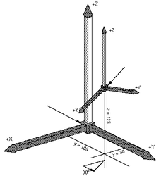
偏航定义
偏航是围绕Z轴相对于前一坐标系的旋转。 前一坐标系是我们旋转的起始坐标系。 该图示出了30°的偏航旋转。 围绕偏角旋转产生新的坐标系(X1, Y1, Z1)。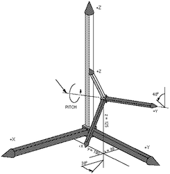
俯仰定义 '偏转旋转后,俯仰是相对于前一坐标系的Y轴旋转。 这意味着围绕新获得的Y1轴进行旋转。下图显示了40°的俯仰旋转。俯仰角的旋转产生新的坐标系(X2, Y2, Z2)。
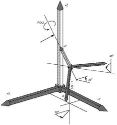
翻滚定义 翻滚是在应用偏航和俯仰旋转之后,围绕Z轴相对于前一坐标系旋转。这意味着翻滚绕Z2轴旋转。 下图显示了20°的横滚旋转。翻滚旋转产生新的坐标系(X3, Y3, Z3)。


| NOTE | |
| 请注意,偏航,俯仰和翻滚顺序的顺序很重要! |
齐次变换矩阵
位置表示的这种方法不是在内部使用的,而是在softMC的用户接口中使用,但它主要用在机器人文献中。 因此,本文档仅供参考,仅供演示和解释之用。 位置变量表示为(4×4)矩阵:
loc = 
这里,xx_axis, yx_axis, zx_axis是定义x轴相对于其初始位置等的变化的归一化值,等...
X,Y,Z是工具中心点相对于机器人底座的位置值。
最后一行(0 0 0 1)用于归一化。
示例 1
if loc坐标为 {100, 80, 150, 45, 0, 0}
loc作为转换矩阵将被写入 :
loc = 
因为如图所示,只有45°的偏航旋转(围绕Z轴旋转)。
通常softMC系统中程序中是{X,Y,Z,Yaw,Pitch,Roll}格式。 这里使用齐次转换矩阵矩阵变换仅用于说明目的。
X Y Z Q (四元数)
- 平移中的3个自由度(X,Y,Z)以mm表示,定义工具中心点相对于机器人底座的位置。
- 使用归一化四元数Q表示的3个旋转自由度,其被描述为围绕矢量n 的旋转的角度phi: [cos(phi/2), sin(phi/2)*n]
四元数旋转的描述由系统内部使用,但不能直接用于用户。 然而,在用户运动学的情况下,必须考虑到这一点。 四元数仅用于说明的目的,softMC系统对所有用户输入和输出使用欧拉角。
关节坐标
对于关节坐标,位置变量由n个分量定义表示每个轴的度(或mm)的值的(n数自由度根据运动学模型的零位置)。
关节坐标中的位置是n个关节值的数组:
Jnt_loc = {jnt1, jnt2, jnt3, jnt4, jnt5, jnt6}
可以通过索引定义以{i}的形式访问各个坐标: Jnt_loc{1}, Jnt_loc{2}, …
上述定义允许我们对关节坐标中的位置执行计算,例如加法,减法等...
Cartesian coordinates
对于笛卡尔坐标,位置变量由6个组件定义,表示值: X, Y, Z, Yaw, Pitch, Roll.
笛卡尔系统变量: here, setpoint
loc = <robot>.here系统维护变量,返回工具尖端参考机械臂参考的WORLD坐标系的当前变换。
笛卡尔位置定义:
系统使用前面带有"#"符号的大括号来区分关节位置和位置位置
#{x_value, y_value, z_value, yaw_value, pitch_value, roll_value}
示例 1
如果"r" 是圆的半径,"angle"是围绕圆的旋转角度,则变换为 :
#{r*COS(''angle''),'' r''*SIN(''angle''), 0, 0, 0, 0}
将在该圆上得到点。.
点操作
复合操作
定义两个笛卡尔点之间的复合运算符。 复合运算符使用':'符号定义。
因此,复合变换写为:
location = loc1 : loc2
这意味着 loc2 是相对于loc1定义的
复合变换是相应的齐次变换矩阵乘以另一个齐次变换矩阵的结果:

或使用四元数:
![{\displaystyle [(X,Y,Z)+Rot_{Q}1(X',Y',Z');Q_{1}\cdot Q_{2}]=[X,Y,Z,Q_{1}]:[X',Y',Z',Q_{2}]}](https://en.wikipedia.org/api/rest_v1/media/math/render/svg/6f1d52a8489be6b54fc6706b86e4440565c175d0)
例子
point_name3 = point_name1:point_name2
point_name3是point_name1和point_name2的复合变换,并在基坐标系(WORLD)中定义。

请注意,必须尊重复合转化的顺序(操作符不可交换)。
例子
hop =#{20,130,45,30,0,90}:point_name
没有定义相同的转换:
hop = point_name:#{20,130,45,30,0,90}
位置逆解
当在空间中控制轨迹时,逆变换对于机器人技术至关重要。 这个概念主要用于坐标系,以将轨迹移动到另一个地方,而无需重新示教点。 定义逆解的函数称为 INVERSE。
逆变换是计算变换矩阵的逆。
INVERSE(loc) = 

或使用四元数:
INVERSE(loc) = 
示例: 逆变换的好处
示例 2
如果"坐标系"是定义圆的中心位置和其所在的平面的变换,则以下程序段将以1度的步长围绕圆周移动机器人终点。
FOR angle = 0 TO 360
MOVE frame:#{r*COS(angle*pi/180), r*SIN(angle*pi/180), 0, 0, 0, 0}
END
MOVE #{10,0,20,0,0,0):HERE:point = HERE is used as a location
位置分配
loc =#{0,0,0,0,0,0}
NULL变换对应于单位矩阵
NULL = 
例子
loc2 = loc1:loc
这里loc是一个NULL转换
loc2 = 
- loc2 is equal to loc1
逆变换和NULL变换
正坐标系变换
直接坐标变换将关节变量(以度为单位)转换为工具点中心(模态值)参考机器人基准(模态值)的位置变量(以mm为单位)。在这种情况下使用的系统功能是: <location> = ToCart(<robot>, <joint position>) 它使用以函数参数给出的机器人的几何数据将一组关节坐标转换为等效变换值。计算出的位置代表世界坐标系中工具末端的位置和方位,考虑到当前的TOOL变换和BASE偏移。
应用:
trans = ToCart (jtloc)
input : jtloc : joint
output: trans : 基于jtloc的给定关节值计算位置
参见: TOCART
例子
以下一系列说明如果通过将关节1旋转10度来改变其当前位置,则计算机器人将移动到的位置和方位。
jtloc = pfb
jtloc {1} = jtloc {1} +10
trans = ToCart(jtloc)
逆坐标变换
逆坐标转换根据配置标志和模态工具和基值将机器人位置转换为关节位置。
在这种情况下使用的系统功能是: <joint position> = ToJoint(<robot>, <location>, <cfg. Flags>) 参见: TOJOINT
{{Note | 从笛卡尔转换为关节坐标可以导致与笛卡尔位置相关联的多种配置解决方案。可以通过更改配置标志强制转换为所需的配置。 }
配置标志的数量和类型取决于每种机器人类型。 下表定义了每种支持的机器人类型的配置标志:
| Robot type | Flag | Values | Bit No. (ToJoint) | |
| 1 | 2 | |||
| PUMA | Arm | lefty | righty | 0 |
| Elbow | below | above | 1 | |
| Wrist | noflip | flip | 2 | |
| SCARA | Arm | lefty | righty | 0 |
| DELTA | - | - | - | |
tojoint函数的配置标志参数定义为:

注意!常量lefty, righty, above, below, flip和noflip被定义为MC-Basic语言的内置常量。
示例
在PUMA RX90机械手中,以下关节点: {0 , -45 , 135 , 0 , 90 , 0} 对应于笛卡尔坐标:
#{768.198 , 0 , 233.198 , 0 , 180 , 0}
和以下配置:lefty, above, noflip。 因此,ToJoint函数的配置标志将被表示为(1-0)*20 + (2-1)*21 + (1-1)*22 = 2。所以相反的方向是:
-->?ToJoint(#{768.198 , 0 , 233.198 , 0 , 180 , 0},0b010)
{0 , -45 , 135 , 0 , 90 , 0}
-->
轨迹插值
关节插值(固有)运动MOVE
MOVE指令为关节插补运动。 也就是说,机器人初始和最终位置之间的中间命令点通过在初始和最终关节位置之间线性插值来计算。运动期间执行程序请求的配置的任何更改。如果在关节坐标上给出了MOVE,则命令配置(acmd,ecmd,wcmd)标志必须与给定目标点的配置标志一致(相同或“自动”)。 关节插值运动由常规MC组参数(vcruise,acc,dec,jerk)确定。
线性插值运动MOVES
MOVES指令为直线运动。在这样的运动过程中,工具中心点沿着直线路径移动并平滑地旋转到其最终方位。在直线运动期间不允许更改配置,除非在命令配置标志以“自动”值给出的情况下,运动允许。直线运动由速度,加速度和加速度的平移/旋转参数对决定:(vtran,atran,dtran,vrot,arot,jrot)。
圆(弧)插值运动CIRCLE
CIRCLE指令为圆或圆弧运动。在这样的运动过程中,工具中心点沿圆弧(或圆)路径移动并平滑地旋转到其最终方位。在圆弧-线运动期间不允许更改配置,除非在命令配置标志以“auto”值给出的情况下,并且运动允许。注意,在圆弧插补的情况下,工具方向将圆形平面上的矢量法线从其初始值旋转到其最终值。圆弧运动由速度,加速度和加速度的转换/旋转参数对决定:(vtran,atran,dtran,vrot,arot,jrot)。
方位插值说明
初始和最终方向以四元数(Qi, Qf) 表示,方向插值将根据公式进行:
![{\displaystyle Q(t)=[cos(\phi (t)/2),sin(\phi (t)/2)\cdot n]Q_{i}}](https://en.wikipedia.org/api/rest_v1/media/math/render/svg/3614cad0c428149e0421675bd35015e1c0ee7951)
其中矢量r 和角度 由以下定义:

![{\displaystyle [cos(\phi (t)/2),sin(\phi (t)/2)\cdot r]=Q_{f}\cdot Q_{i}^{-1}}](https://en.wikipedia.org/api/rest_v1/media/math/render/svg/202eeb84c24435bc733dcf57d625d536c6aa42ed)
角度的变化率与机器人运动的WORLD位置(X,Y,Z)的变化率成比例。
上述公式的角度phi可以总是在两个方向上改变:正和负。一个会比另一个更短一些,但这并不需要在关节空间中给出更短的移动。 因此,用户可以使用机器人的OrientationFollowing属性来影响方位插值。 方向跟随属性的值为:
0 – 世界坐标下最短路径(最短方位路径)
1 – 关节坐标最短路径(SCARA第四关节最短运动)
2 - 在世界空间更长的路径 3 - 在关节空间更惨的路径 4 –世界空间的正方向
5 – 关节空间的正方向 - 最后关节标志
6 – 世界空间负方向
7 – 关节空间负方向 - 最后关节标志
参见:
关于运动的一般注释
插值类型和目标点有四种不同的组合。 目标点可以以世界或关节坐标中给出,并且插值可以是直线或关节插值(固有)。 对于 直线 (笛卡尔插值)运动的两种情况,适用以下规则:
- 运动中Arm-flag(afbk)的实际值不会改变。 它的初始值和最终值必须相同,除非运动开始形成标志的“自动”值。
- 在运动过程中,Elbow - flag(efbk)的实际值不会改变。它的初始值和最终值必须相同,除非运动开始形成标志的“自动”值。
- 在运动过程中Wrist –flag(afbk)的实际值不会改变。它的初始和最终值必须相同,除了两种情况:一是运动开始时形成标志的“自动”值。二是当wcmd具有“自动”值,并且运动通过手腕奇异性(pcmd {5} = 0)时,不影响第四和第六关节。
使用关节目标(MOVES {…,…,…})的直线运动在笛卡尔空间插值,因此XYZ坐标的变化是线性的。 用户可以指定配置命令标志(acmd,ecmd,wcmd),但它们必须符合给定的目标点。 如果由于某种原因(通常是方向跟随),在关节空间(在世界空间中始终达到!)不会达到给定的目标点!将会生成错误。 通常,最后三个关节可以达到±360度不同的其他值,但笛卡尔点是相同的。
在这种情况下,OrientationFollwing标志将被忽略,并且所有的计算都将在用户设置值1(关节空间中的最近路径)的情况下完成。
使用笛卡儿目标(MOVES #{…,…,…})的直线运动在笛卡尔空间插值,因此XYZ坐标的变化是线性的。 用户可以指定配置命令标志(acmd,ecmd,wcmd),只允许正确设置,否则将返回错误。
关节 –具有关节目标(MOVE {…,…,…})的关节插值运动在笛卡尔空间插值,所以j1,...,j6的变化是线性的。 配置标志被忽略。
关节 –用笛卡尔目标(MOVE #{…,…,…})的关节插值运动在笛卡尔空间插值,所以j1,...,j6的变化是线性的。 计算目标坐标时考虑配置标志。 如果选择“自动”配置标志,则将选择最接近目标的点。
配置标志选择无效的情况
通常,系统不允许在笛卡尔插值运动(MOVES,CIRCLE,PASSTHROUGH)期间进行配置标志更改,如果此类命令更改将返回错误,并且运动将不会启动。 当命令配置标志(acmd,ecmd,wcmd)与起始点(afbk,efbk,wfbk)上的反馈配置标志不同时,会发生这种情况。 但是,根据特定的机器人型号,当命令标志为“auto(0)” 值时,系统将选择与起始位置相同的配置,但存在异常。
在PUMA运动学中,有些特殊情况下笛卡尔插值运动期间配置标志可以改变
当wcmd设置为“auto(0)”并发出直线运动之一时,WRIST 标志可以更改。 如果这样的动作通过第五关节角度的全部零,那么手腕标记就会改变。 然而,这可能会引起关节4和6的相反旋转。如果此旋转太快,将返回错误信息,并且将取消运动。为了防止用户在这些点附近命令低笛卡尔速度(vrot,vtran)。
在直线运动(MOVES)通过臂点奇点的情况下,可以获得 ARM和 ARM标志的改变,在PUMA机器人d2 = 0的情况下,点X = 0,Y = 0,Z = a2 + d4 + d6,或者在d2≠0的情况下(RX60)为圆X = d2cosα,Y = d2sinα,Z = a2 + d4 + d6。

以关节坐标给出的目标点的运动受到不同的对待。 在这些情况下,目标关节坐标和命令配置标志必须符合(相同或具有自动值)。 如果不是这样,运动将不被执行,并且将返回错误。
用户坐标系
oftMC系统丰富了一组用户可定义的工作坐标系。 所有工作坐标系模式和节点都可用。 所有用户坐标系必须具有与父机器人相同的位置类型(XYZ,XYZR,XYZYPR ...)。
使用机器人提供以下用户可定义的坐标系:
- 世界坐标系。缺省笛卡尔坐标系。 这个坐标系通常位于机器人底座。
- 基坐标系。从用户角度来看机器人坐标系。 通常用于校正安装旋转或倾斜机器人。(可用于吊装的机器人)。
- 工具坐标系。坐标系连接到安装在机器人上的工具,与工具几何形状密切相关。 用于描述所附工具所做的任务(磨削,去毛刺,拧紧,...)
- 工作台坐标系 机器人使用的工作台坐标系
- 工件坐标系。机器人使用的工作台上工件的坐标系

机器人的所有位置属性始终以整个用户坐标系表示,因此始终位于整个用户坐标系链所定义的工件坐标系中。 使用之前定义的复合变换,我们有:
| NOTE | |
| 设置新值时, 工具 属性会导致位置误差(pe)的显着增加。pe 的值始终在工具尖端计算,因此增加工具具长度和小方向误差可导致pe增加。 将pe置于以下的方程式中是很明显的: |
工具
工具是一个Robot属性,它通知系统使用指定的位置作为 工具 转换。它定义工具尖端相对于工具法兰中心的位置和方向。 默认的工具转换是NULL转换,可以表示为TOOL = #{0,0,0,0,0,0}
例子
Puma.tool = #{25,0,100,0,45,0}
基座标
基座标是一个Robot属性,它通知系统使用指定的位置作为base转换。 它根据WORLD参考来定义机械臂连杆的位置和方向。
默认的基坐标变换是NULL变换,可以表示为Puma.base =#{0,0,0,0,0,0}
工作台
工作台是一个Robot属性,它通知系统使用指定的位置作为工作台变换。 它定义了相对于BASE参考的位置和方向机床工作坐标系。
默认的工作台变换是NULL变换,可以表示为Puma.MachineTable =#{0,0,0,0,0,0}
工件
工件是一种Robot属性,通知系统使用指定位置作为工件变换。 它定义了参考MACHINE TABLE的工件的位置和方向。
默认的基本变换是NULL变换,可以表示为Puma.WorkPiece =#{0,0,0,0,0,0}


因此有:
Pbase=Base:Pworld:Tool
Pbase=MachineTable:WorkPiece:PWorkP
对于给定的设置用户坐标系将是:
Base = #{300,200,1000,0,180,180}
Tool = #{50,0,0,90,45,0}
MachineTable = #{400,100,0,0,0,0}
WorkPiece = #{20,70,150,0,90,-90}
因此有:
PWP= WorkPiece-1: MachineTable-1:Base:PWorld:Tool
副作用
以模态(工具,基座,工作台,工件设置任何用户框架,可立即对所有位置计算产生影响::
- Setpoint
- Here
- Start
- Dest
- ToJoint
但不影响目前的运动。