RoboDK
Contents
Using RoboDK
How to assign a robot to RoboDK from STEP files
The main purpose of this section is to teach the user, step by step, how to assign a new robot to RoboDK by using STEP files.
First of all we'll need the appropriate STEP files. Only after receiving those files we can start working.
Our primary goal is to create several STEP files that separately contains the robot's joints parts.
The meaning is that every file contains all the robot's parts that move together along the same axis.
It's preferred off-course to receive all files separately, but mostly the hole robot will be sent as one file.
step 1
Inside that file, the robot is divided to it's joints parts (for example: base, joint 1, joint 2).
- Open the file in SolidWorks.
- Figure out the structure of the robot.
- check if actually divided to the needed joints parts.
- If not divided correctly to the appropriate sub-assembles, we'll need to do that by ourselves.
- Mark all the parts and sub-assembles that move around the same axis and unite them to the same sub-assembly.
- Save and name that sub-assembly with the appropriate joint name (base, joint 1, joint 2).
step 2
Now that we have our sub-assembly's corrected as the right base and joints, the next step is to assign the correct orientation for the robot.
- In SolidWorks, the default orientation is that the base is parallel to the XZ plane.
- Move the robot to be parallel to the XY plane.
step 3
Centralizing the robot relatively to it's base:
- Define the base center.
- Centralize all joint's sub-parts that supposed to be centralized, relatively to the defined base center.
step 4
Define all parts in every sub-assembly separately:
- Every sub-assembly has parts that integrate differently with one another.
- Some are concentric, some are linked and some have fixed distance between them, all of this features must be defined correctly if they are not defined already.
- Define the connections above for every possible part in the sub-assembly (including trademarks/symbols and so forth).
- Make sure they're parallel to the right plane and move around the right axis.
step 5
Save every sub-assembly as a STEP.AP2M file
step 6
Open the files in RoboDK. Now we'll define the robot's utilities with RoboDK.
- Go to 'Utilities' --> 'Model Mechanism or Robot', the following window will appear.
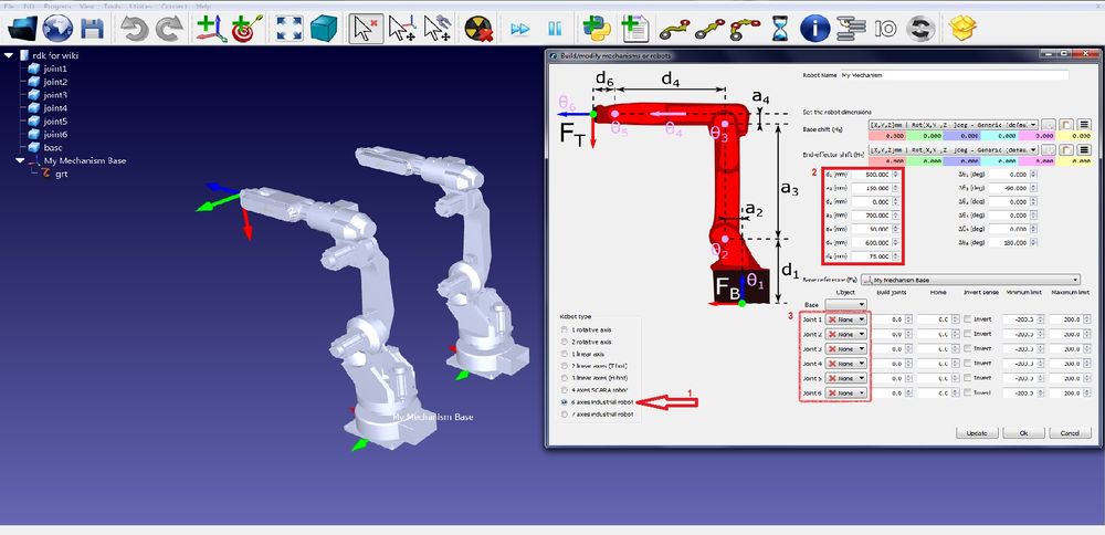

- Choose the type of robot.
- Measure the robot with SolidWorks and assign the appropriate measures for every link of the robot.
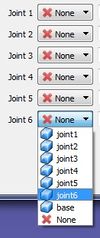
- Choose the correct graphics for every link from the sub-assembles we created.

step 7
Try to move all joints separately. If they do not move as they should, go back to step 6.3 and try to play with the values of the various joints.

If the robot is still acting not as expected, go back to step 6.2 it may be that the measuring is incorrect.
another option is to go back to step 4 and check if every part is defined properly.