Input/Output
Contents
Introduction
The softMC does not have local I/O, but can map drive inputs and outputs as well as I/O extension modules to its SYS.DIN and SYS.DOUT
Local I/O softMC
softMC (CANOpen and EtherCAT) does not have local I/O.
For backward compatibility sys.dout.1 to sys.dout.20 can be read and written but do not have any function.
Value of sys.din.1 to sys.din.23 is read from file IO.DAT, from field "INP"
File IO.DAT is generated automatically if it does not exist on the flash disk.
Format of IO.DAT
DIP=0xXX
INP=0xXX
Software I/O softMC
Bit-oriented Software I/O
Software I/O is used in the softMC program just like standard I/O. Standard inputs are accessed with SYSTEM.DIN.1 through DIN.23, and virtual inputs are accessed with SYSTEM.VIN.1 through VIN.32. Standard outputs are accessed with SYSTEM.DOUT.1 through DOUT.20, and virtual outputs are accessed with SYSTEM.VOUT.1 through VOUT.32. You can use software I/O to start events just as with standard I/O. Programmable limit switches can use software outputs just as with standard outputs. Here is an example:
OnEvent SoftwareInputEvent System.VIn.1 = ON
System.VOut.1 = OFF
If(System.VOut.4 = ON)
. . .
Long-Word-Oriented Software I/O
The entire word (32 bits) of software input and output is accessed when a bit position is not included in the reference to the input or output variable. So the following statement is valid:
System.VOut=System.VIn
This statement copies the virtual software input to the output. The physical input and output variables are used in this manner. Be careful when assigning virtual I/O to physical I/O because there are fewer physical bits than there are virtual bits. There are only 20 bits of physical output, but the virtual output variable can have 32 bits.
PLS - Programmable Limit Switch
Replaced by NEW PLS article - Programmable Limit Switch
A Programmable Limit Switch (PLS) monitors position feedback on any axis, real or simulated. A PLS offers more flexibility than a limit switch, as it allows many trip points and can be reconfigured on-the-fly. A PLS toggles the state of a specified system output when an axis position reaches any of the defined positions of the PLS. Some of the features of a PLS are:
- Multiple position specifications.
- Multiple PLSs per axis
- PLS pattern repetition
- Position hysteresis
- Enabling and disabling of PLSs
- The system output may be digital or soft (fast data)
PLS positions are defined in an array that allows you to change individual values of PLS positions. This array must be increasing monotonic. There is no limit of the number of positions or PLSs that can be defined.
The initial output polarity is specified with PLSPOLARITY. The output state is set when the PLS is enabled.
Enable and Disable
After being defined, a PLS is disabled (output pattern is not generated). The output is set when the PLS is enabled. The output is set to the defined initial state.
PLS properties are changed only when the PLS is disabled. Each enabled PLS requires CPU resources. Conserve those resources by disabling the unused PLS(s). PLSENABLE controls the status of the PLS:
MyPLS.PlsEnable = ON | OFF
PLSENABLE queries the status of a PLS:
?MyPls.PlsEnable
if(MyPLS.PlsEnable = OFF)
. . .
or drives events:
EventOn MyEvent MyPLS.PlsOutput = ON
Switch Positions
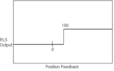
The basic mechanism of the PLS is the switch position(s) where the PLS output changes state. The figure belows shows a PLS output with one switch position at 100.
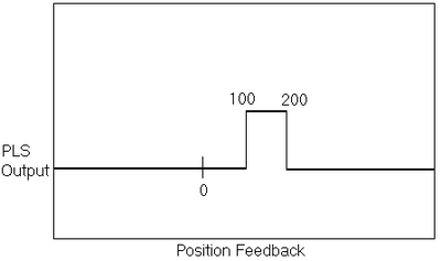
More switch positions can be added. To have the PLS in the above example turn back off at 200, simply add a second position at 200 as shown below:
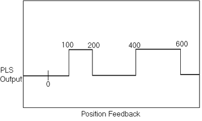
You can add any number of positions. For example, to extend the above example to turn back on at 400 and off again at 600, add positions 3 and 4 as 400 and 600 as shown below:
There is no explicit limit to the number of positions you can have in a PLS, but the PLS positions must be increasing monotonic (Position2 must be greater than Position1, Position3 must be greater than Position2, etc.).
Repetition Interval
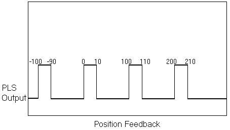
PLSREPEAT allows you to repeat the same PLS after a fixed number of counts. For example, the figure below shows a PLS that turns on at 0, off at 10 and has a PLSREPEAT value of 100:
Polarity
PLSPOLARITY allows you to control the polarity of the PLS output. The initial polarity may be specified as 1 or 0, indicating that the output is set to 1 or 0 after the PLS is enabled and when the axis is located between the first and second PLS positions. If the axis position (when the PLS is enabled) is not located within this segment, the output polarity is set to 0 or 1, according to the current position so that when the axis reaches the first segment, the output polarity is as indicated. The default value for polarity is 0.
Hysteresis
The softMC allows you to apply hysteresis around switch points. Hysteresis provides a margin in the switching between PLS positions to accommodate noise in the PLS axis. Set the hysteresis greater than the noise on the axis, (typically, 5 or 10 counts of encoder is sufficient, less is required for resolver systems). If you have a hysteresis of 0.01 position units, each transition of PLS position is moved forward 0.005 units for positive motion and backward 0.005 units for negative motion. If the axis driving the PLS is stopped directly on a PLS position and the inherent noise on the axis is less than the hysteresis, the PLS state does not change due to this noise.
Enable and Disable
PLSENABLE enables or disables the PLS(s). After being defined, a PLS is disabled. The output is fixed when the PLS is enabled. The PLS output is set to the defined initial state when the PLS is enabled.
PLS Output State
Query the digital output associated with the PLS to query the state of the PLS output. For example, assume the PLS output is assigned to SYSTEM.DOUT.1. To determine the output state of the PLS, query the state of SYSTEM.DOUT.1:
-->?Sys.Dout.1
0 | 1
Set Up
Step 1
Declare the PLS with Common Shared <var> as PLS in Config.Prg or at the terminal. You must name the PLS, specify the axis that drives the PLS, and name an output to be controlled by the PLS. For example:
Common Shared MyPLS as PLS A1 System.Dout.1
sets up MyPLS as a PLS driven by axis A1 connected to SYSTEM.DOUT.1. The output can be a digital output (SYSTEM.DOUT.1 through DOUT.20) or it can be one of the virtual outputs (SYSTEM.VOUT.1 through VOUT.32).
After the Common Shared <var> as PLS executes, the PLS is disabled. Properties of the PLS are set as:
- A single PLS position exists at 0.
- The initial output polarity is 1.
- PLSREPEAT is set to 0.
- The hysteresis is set to 0.
These properties may be set explicitly, as long as the PLS remains disabled. You can check which output is associated with a given PLS using PLSOUTPUT.
Step 2
Create the PLS data structure and define PLS positions. The number of defined positions is not explicitly limited. A call to CREATEPLSDATA creates an array of n positions that stores the position data. The array is 1-based and an error is generated if you attempt to access an index outside of the array bounds. For example:
CreatePLSData 4 MyPLS
MyPLS.PLSPosition[1] = 1000
MyPLS.PLSPosition[2] = 1100
As a short form, you can use PPOS in place of PLSPOSITION:
MyPLS.Ppos[3] = 2000
MyPLS.Ppos[4] = 2200
You cannot change PLS positions when the PLS is enabled. Position values must be increasing monotonically.
Step 3
Set the polarity. PLSPOLARITY defaults to OFF, indicating the PLS state should be OFF after the first position. Change PLSPOLARITY to ON to invert the state.
MyPLS.PLSPolarity = ON
Change PLSPOLARITY only if the PLS is disabled.
Step 4
Set PLSREPEAT. If you want the PLS to repeat, set the value of PLSREPEAT to a non-zero, positive number. For example, to have the PLS repeat every 10,000 position units, enter:
MyPLS.PLSRepeat = 10000
PLSREPEAT defaults to 0, indicating that there is no repetition. Change PLSREPEAT only when the PLS is disabled.
Step 5
Set PLSHYSTERESIS, if the application requires it. Hysteresis is only necessary if the system does stop on or near a PLS position. Normally, a PLSHYSTERESIS of 5 or 10 counts of encoder (converted to position units) or 2 or 3 counts of resolver resolution is sufficient.
MyPLS.PLSHysteresis = 0.01
Step 6
Enable the PLS. Enter:
MyPLS.PLSEnable = ON
There are a few other PLS functions you may need:
Change Polarity The default output state of a PLS is 0. Change this initial state by modifying PLSPOLARITY.
MyPLS.PLSPolarity = 1
The PLS must be disabled when changing this setting.
Query the Name Query the name of the axis driving the PLS:
? MyPLS.PLSAxisName
returns the axis associated with the PLS (A1).
Disable the PLS Disable the PLS. For example:
MyPLS.PLSEnable = OFF
You must disable a PLS to change PLS properties. Disabling a PLS also helps conserve CPU resources.
Delete a PLS Delete a PLS to remove it from the system only when the PLS is disable and there are no tasks in memory. For example:
DeletePLS MyPLS
External Encoders
The softMC supports external encoders (encoders not connected to an axis controlled by the softMC). These encoders are connected to the system using the external encoder input of any drive in the system. You can access the encoder periodically with:
? IDNValue(<''axis''>.DriveAddress, 53, 7)
‘Query external encoder position
If you are using the encoder for master/slave operation or in a way that requires the value of the signal be updated to the softMC every SERCOS cycle, you must configure the telegram for that axis as Telegram type 7. You also must specify that external position must be included in the telegram. This command is only available when in communication phase of 2 or higher.
Access to Legacy I/O and ISA
The softMC offers support for access to legacy ISA devices located in low memory(0xA0000 - 0xE0000).
Commands
The softMC supports memory and I/O instructions.
If you are using memory-mapped devices, you will need the memory access commands, PEEK and POKE. The valid memory address range for PEEK is 0xA0000 through 0xDFFFF. The valid memory address range for POKE depends on the hardware version of the softMC card.
For the ISA-Bus card, the valid memory address range for POKE is 0xA0000 to 0xCFFFF and 0xDA000 to 0xDFFFF.
For the PCI card, the valid memory address range for POKE is 0xA0000 to 0xC7FFF and 0xDB000 to 0xDFFFF.
- PEEKB transfers byte-wide (8-bit) data from the bus to a variable.
- PEEKW transfers word-wide (16-bit) data from the bus to a variable.
- POKEB transfers byte-wide (8-bit) data to the memory bus.
- POKEW transfers word-wide (16-bit) data to the memory bus.
If you are using I/O-mapped cards, you need INP and OUT.
- INPB transfers byte-wide (8-bit) data from the I/O bus to a variable.
- INPW transfers word-wide (16-bit) data from the I/O bus to a variable.
- OUTB transfers byte-wide (8-bit) data to the I/O bus.
- OUTW transfers word-wide (16-bit) data to the I/O bus.


