6-Axis Puma robot Setup
| Language: | [[::6-Axis Puma robot Setup|English]] • [[::6-Axis Puma robot Setup/zh-hans|中文(简体)]] |
|---|
This is a tutorial for a 6-axis PUMA robot setup with the Configurator.
Contents
Creating and Running a CONFIG.PRG file
The Configurator does not generate a CONFIG.PRG file, which is a necessary file.
The most simple CONFIG.PRG file will look like this:
Sys.NumberAxes = 6
program
    Sys.Name = "MC_NAME"
    Print "system is running  -  " ; Sys.Name
end program
NOTE: It is important that Sys.NumberAxes will be at least 6 as the puma robot needs 6 axes.
Before opening the Configurator, please run the CONFIG.PRG file by uploading it to the softMC and sending "reset all" in the terminal.
Opening The Configurator
First, you need to open the configurator. One option is to open the configurator through the Control Studio.
Go to: tool → softMC Configurator.
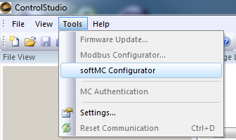
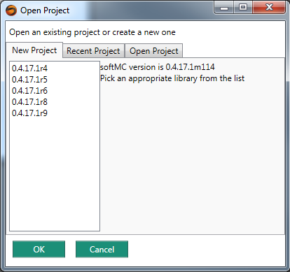
If the Control Studio is already connected to an MC, then you will see the following window.
Choose the New Project tab, and then choose the softMC version that is on your softMC.
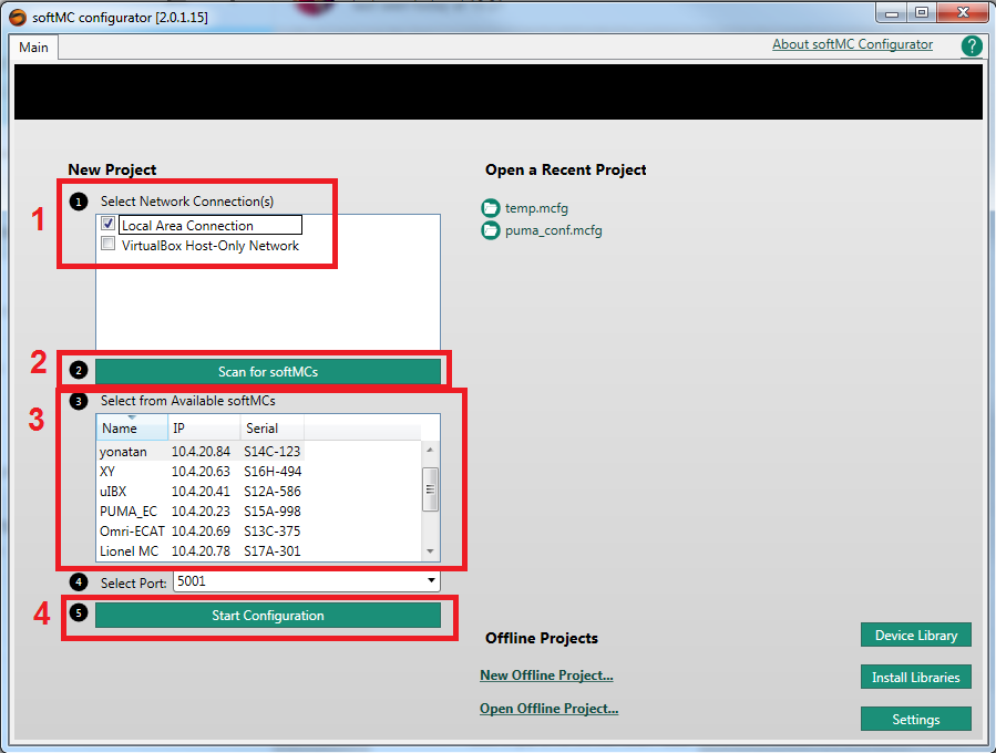
If the ControlStudio was not connected to the softMC, the next window will be shown.
1. Choose the type of network connection
2. Press on "Scan for softMCs"
3. Choose your softMC
4. Press on the "start configuration" button
Then you will get to the previous explained window. Follow the previous instructions.
Configuring The Drive and Axes
First, you need to configure the drives and axes.
In the project window, the left pane shows the recognized drives and axes.
Note: Only EtherCAT drives are recognized automatically, the CANopen drives should be added manually.
Note: If a simulative robot is being configured, ignore the drives configuration part.
Drives
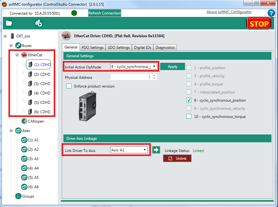
Press on the first drive and its configuration window will show:
The minimum requirement are:
- Choose the "Initial Active OpMode". Please choose: "8 - cyclic_synchronous_position".
- Link the drive's corresponding axis. Choose the correct axis in "Link Driver To Axis".
- Lastly, press on the "Apply" button.
Repeat the last steps for each used drive.
Axes
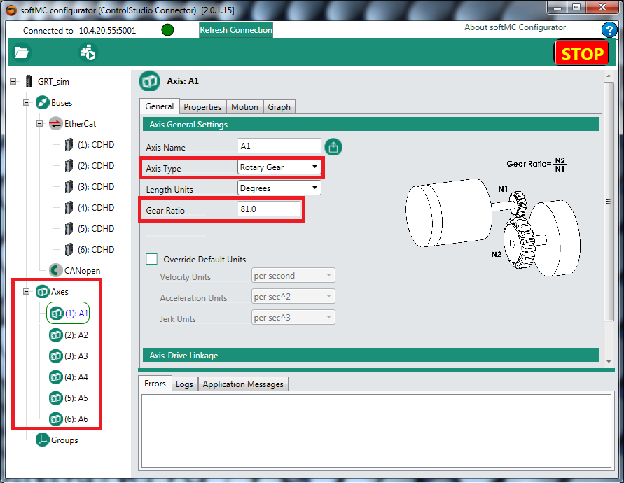
Press on the first axis and its configuration window will show:
The minimum requirement are:
- Choose the "Axis Type". Please choose: "Rotary Gear" for the PUMA robot.
- Set the Gear Ratio value to the correct value.
Repeat the last steps for each used axis.
The configuration window of the axes has few tabs.
The "Properties" tab allows to set the axis properties. For example, this is how you can set the direction of each joint:
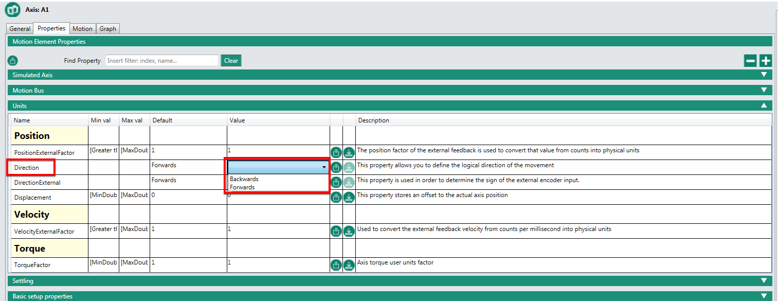
Please set the properties appropriately to each axis based on demands and manufacture instructions.
Note: If the configuration is for a simulated robot, change the "Simulated Axis" property to "True" for all axes.
Configuring The PUMA Robot
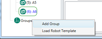
Right click on the "Groups" icon in the left pane, and choose "Add Group".
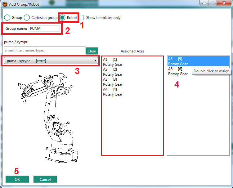
In the popup window, follow these steps:
- Choose "Robot"
- Set a "Group name" (in the example the name is PUMA)
- Choose the "puma xyzypr" robot
- Add the relevant axes to the "Assigned Axes" list by double-clicking on them. When a correct set of axes is chosen, the "Assigned Axes" box will become green
- Press the OK button
Now, the robot/group configuration window will be shown. There are few tabs to look at:
General tab
This tab allows to switch the axes which are linked to the group and to change the axes properties
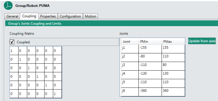
Coupling tab
This tab allows to set:
- The coupling matrix for the robot (which usually shouldn't be changed for a puma robot).
- The joints position limits.
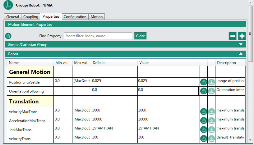
Properties tab
This tab allows to set the robot properties, such as: position limits, speed limits, acceleration limits, etc.
Configuration tab
This tab has 3 sub-tabs:
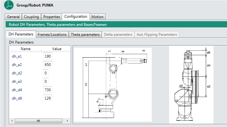
DH Parameters tab
This tab allows to set the DH parameters of the PUMA robot. Please set these values corresponding to the drawings supplied in this tab.
Frames/Locations tab
This tab allows to set the PUMA robot location vectors, such as where the robot base is located, or the position of the tool relative to the 6th joint frame.

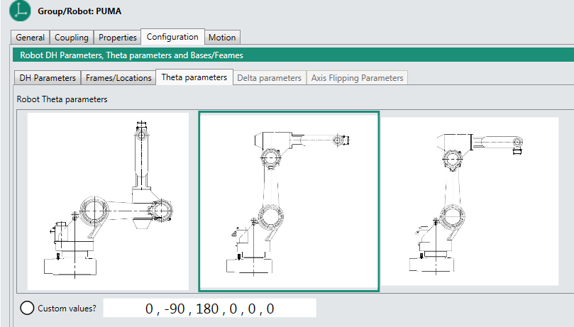
Theta Parameters tab
This tab allows to set the PUMA zero location. The default zero location of the PUMA robot is as in the left image.
You can choose one of the other options for the zero location - just press on the desired image to set this configuration as the zero location.
You can also define a customized displacement to each axis in order to set a customized zero location.
Generate and Run The Setup Files
Finally, after the configuration is done, you can generate the setup files and run them on the MC by pressing on the "Build & Configure" icon (see image).
![]()
The generated files are:
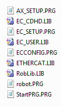
When pressing the "Build & Configure" icon, these files are automatically sent to the MC and being executed. Now the MC is loaded with your configuration and the robot is ready to be used.
After shutdown or reset of the MC, all you need to do in order to load your configuration is send: "reset all" and then "load startprg.prg" through the Control Studio's terminal.
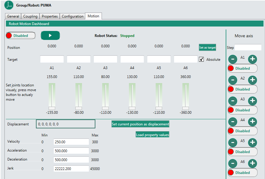
Motion tab
This tab allows to move the robot and test the configuration only after the configuration files have been built and ran successfully. The GUI is similar to a TP GUI.
Robot Programs Example
Now you are ready to run robot programs.
To learn about Control Studio and MC-Basic, visit: Getting Started with MC-Basic and ControlStudio.
To learn about some basic robot programs, visit: Robot Pick & Place, Robot Circle, Robot Helix
For more motion program examples, visit Motion Examples
