Axis Setup Procedure
Contents
- 1 Introduction
- 2 Step 1: Declare Axis
- 3 Step 2: Setting Meaningful Axis Name
- 4 Step 3: Preparing General Axis Setup
- 5 Step 4: Position Units Definition
- 6 Step 5: Moving Direction
- 7 Step 6: Velocity, Acceleration, Jerk Units
- 8 Step 7: Units Summary
- 9 Step 8: Position Limits
- 10 Step 9: Motion Bus Units Setup
- 11 Step 10: Motion Parameters
- 12 Step 11: Safety Parameters
- 13 Step 12: Smoothness
- 14 Step 13: Axis Setup Complete Example - the SetAxis Subroutine
- 15 Step 14: Motion-Bus EtherCAT Example
- 16 Step 15: Extra - Dynamic Model
Introduction
This series of slides will explain how to create and set an axis in the softMC controller. For that you will need:
- Running softMC (either a real, or virtual)
- User interface (Control.Studio)
Step 1: Declare Axis
In the first line of CONFIG.PRG file write the number of axes that will be in use:
Sys.Naxes = <number>
…
Program
…
End Program
Send this file to MC and run it by issuing these two lines from terminal window:
send config.prg
reset all
Now you have your axes defined, it is easily to check issuing this command from terminal window:
->?axislist
A1,A2,A3,A4,A5,A6,A7,A8,A9,A10,A11,A12,A13,A14,A15,A16,A17
Step 2: Setting Meaningful Axis Name
System default axis names are not very user friendly (a1,a2,a3, etc.). It is a good practice to give them more meaningful names. This is done in CONFIG.PRG file only, by assigning a new name to each axis (no double-quotes) to <axis>.AxisName property.
Sys.Naxes = <number>
…
Program
	a1.AxisName = Xaxis
	a2.AxisName = Lift
…
End Program
Step 3: Preparing General Axis Setup
To set up system axes, a setup program must be prepared. Let’s call it SETUP.PRG.</br> It is important to know:
- To access (write to) an axis property, the axis needs to be attached.
- For some properties, the axis needs to be disabled
SETUP.PRG
Program
	Call SetAxis(a1)
	Call SetAxis(a2)
	…
End Program

Sub SetAxis(ax as generic  axis)
With ax
	Attach
		En = 0
		…
		<stuff goes here>
		…
	Detach
End With
End Sub
Step 4: Position Units Definition
<axis>.PositionFactor defines the position units that will be used in all position variables of the specified axis (pcmd, pfb, etc.). It consists of:
- Motor encoder resolution seen through the motion-bus (See EtherCAT, SERCOS, CanOPEN). How many counts are there in one motor revolution - stored in pos_units global variable (for each axis differently).
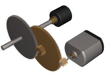
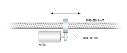
- Gear ratio (M:N) and/or the pitch of the linear screw (mm/rev).
- Rotary axes:
- For position in degrees PositionFactor is:PFAC = Pos_Units *(M/N)/360
- Linear axes:
- For position in millimeters PositionFactor is:PFAC = Pos_Units)/MPITCH
See Motion Bus setup for pos_units and MPITCH setup
Step 5: Moving Direction
Positive direction of drive's position increments does not have to match the desired positive direction of user axis (Upwards, Left-Right, Counterclockwise). Therefore <axis>.direction flag is to be used:
<axis>.Direction = {1|-1}
Value of -1 indicates direction inversion.
Step 6: Velocity, Acceleration, Jerk Units
Velocity/acceleration/jerk units do not have to match position units. The user may select the units. For all the derivative units (velocity, acceleration, jerk), the default time scale is in milliseconds; therefore scaling is needed.
To use position units per second for velocity the following must be defined: <axis>.VelocityFactor = <axis>.PositionFactor/1000 In this case if the user sets the position in millimeters the velocity will be mm/sec
To define velocity in RPM of the motor:
<axis>.VelocityFactor = Pos_Units /1000/60
Acceleration and jerk units are the same; their default values are expressed in velocity and acceleration units per milliseconds. Thus, in order to set them per seconds, they need to be set as: <axis>.AccelerationFactor = <axis>. VelocityFactor /1000 <axis>.JerkFactor = <axis>. AccelerationFactor /1000
Step 7: Units Summary
Position, velocity, acceleration and jerk units are set by:
- <axis>.PositionFactor = …
- <axis>.Direction = …
<axis>.VelocityFactor = ..
- <axis>.AccelerationFactor = ..
- <axis>.JerkFactor = …
Step 8: Position Limits
Setting position range of an axis. Setting max position:
<axis>.Pmax = … and enabling /disabling it: <axis>.PmaxEn = {0|1}
Setting min position:
<axis>.Pmin = … and enabling /disabling it: <axis>.PminEn = {0|1}
Setting the axis type:
<axis>.AxisType = 0 ‘ For linear axes
<axis>.AxisType = 1 ‘ For rotary axes
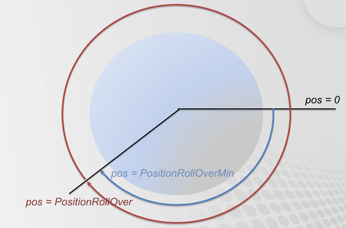
For rotary axes rollover can be defined: Enabling/Disabling it:
<axis>.PositionRollOverEnable = {0|1}
Setting the whole range:
<axis>. PositionRollOver
Setting the low value:
<axis>. PositionRollOverMin
Note: If the enable flag is not set, the corresponding value does not need to be set.
Step 9: Motion Bus Units Setup
Depending on the type of motion bus (EtherCAT, SERCOS, CANopen) and drive used, several parameters are available for the user to adjust (but are not necessarily needed):
If micro-interpolation is turned on in the drive, the velocity sent to drive must be properly scaled; this is done with (for counts per ms):
- <axis>.MotionBusVelocityScale = 0
- <axis>.MotionBusVelocityBase = 1
If a limited drive’s position range is used (other then integer 32 bits):
- <axis>.CountMin = < drive min position value>
- <axis>.CountMax = < drive max position value>
Step 10: Motion Parameters
Motion parameters are grouped into velocity, acceleration and jerk values. All have maximum values for overall limitations, and motion-default values that are used when motion is executed.
| Motion default value is: | <axis>.VelocityCruise |
Velocity is set according to maximum axis physical limit (drives/motor capabilities and mechanical limitations):
<axis>.Vmax
| Motion default values are: | <axis>.Acceleration <axis>.Deceleration |
Acceleration is set according to maximum axis physical limits (Max drive/motor current, axis load) in user units:
 <axis>.Amax
 <axis>.Dmax
| Motion default value is: | <axis>.Jerk |
Jerk is the third time-derivation of position, if smooth profiles are used it needs to be defined a good rule of thumb is to set J=BW*A, where J – jerk, A – acceleration, BW- control Bandwidth (Hz).
<axis>.JerkMax
Step 11: Safety Parameters
Maximum allowed position error (PE). PE is defined as a difference between the position command and position feedback. Due to communication delay of the motion bus and processing time of the drive (micro-interpolation) position command of the several samples before the current is compared to the currently obtained position feedback of the drive:
 <axis>.PositionErrorMax – max allowed position error during in user units.
 <axis>.PositionErrorDelay – number of samples used for delay computation.
Velocity (Runaway) Protection, the feedback velocity of the motor is checked every sample (recommended to be set to 120% of the <axis>.VelocityMax)
<axis>.VelocityOverSpeed
Sanity Threshold, as a final protection against unintentional jumps (recommended to be set to 1000% of <axis>.VelocityMax):
<axis>.VelocitySafetyLimit
Torque Error – only if axis dynamic model is turned on
<axis>.TorqueMaxError
Step 12: Smoothness
Different profile types are available from very smooth S-curves (Acceleration Trapeze, Sine Acceleration) to less smooth by faster Velocity Trapeze, to totally edgy profiles (Constant Velocity) by setting these two parameters:
<axis>.Smooth defined automatic (0-100) or manual smoothing (-1) <axis>.PrfType specifies profile more precisely (Velocity Trapeze, Acceleration Trapeze, Sine Acceleration)
Step 13: Axis Setup Complete Example - the SetAxis Subroutine
sub SetRotAxis(ax as generic axis, byval minval as double , byval maxval as double)
  with ax
    attach
      En = 0
      AxisType = 1
      PositionFactor = pos_unit/360
      VelocityFactor = PositionFactor /1000
      AccelerationFactor = VelocityFactor /1000
      Jerkfactor = AccelerationFactor /1000
      VelocityMax = 1000
      AccelerationMax = 10000
      DecelerationMax= 10000
      JerkMax = 20*amax
      VelocityCruise = 0.5*VelocityMax
      Acceleration = AccelerationMax
      Deceleration = DecelerationMax
      Jerk = JerkMax
      PrfType = -1
      Smooth = -1
      VelocityOverspeed = 1.2*VelocityMax
      VelocitySafetyLimit = 10*VelocityMax
      PositionErrorDelay = 2
      PositionErrorMax  = 1
      PositionMax = maxval
      PositionMin = minval
      PositionMaxEn = 1
      PositionMinEn = 1
      PositionRolloverEnable = 0
   detach
  end with
end sub
Step 14: Motion-Bus EtherCAT Example
Position Units
- First read the motor encoder resolution (MENCRES – SDO:0x20F1:0)
- MENCRES = EC_SDO_READ(<addr>,0x20f1,0)
Then set (value of 1) the configured number of motor shaft revolutions and number of driving shaft revolutions. The gear ratio is calculated by the following:
- Fieldbus CANopen Gear Motor Shaft Scaling (FBGMS – SDO0x2091:0)
- Fieldbus CANopen Gear Driving Shaft Scaling (FBGDS – SDO0x2091:1)
- gear ratio = FBGMS / FBGDS
Step 15: Extra - Dynamic Model
Torque Scaling
- <axis>.TorqueFactor – according to the Motor KT parameter
Limits
- <axis>.TorqueMax – maximum motor torque
Dynamic Model Parameters
- axis.DYNAMICMODEL[..] = <…>


