Axis Setup Procedure
Contents
- 1 Introduction
- 2 Step#1: declare axis
- 3 Step#2: Setting user friendly axis name
- 4 Step#3: Preparing general axis setup
- 5 Step #4:Position Units definition
- 6 Step#5: Moving Direction
- 7 Step#6: Velocity, Acceleration, Jerk units
- 8 Step#7:Units summary
- 9 Step#8:Position Limits
- 10 Step#9: Motion Bus Units Setup
- 11 Step#10: Motion Parameters
Introduction
This series of slides will explain how to create and set an axis in the softMC controller. For that you will need:
- Running softMC (either a real, or virtual)
- User interface (Control.Studio)
Step#1: declare axis
In the first line of CONFIG.PRG file write the number of axes that will be in use:
Sys.Naxes = <number>
…
Program
…
End Program
Send this file to MC and run it by issuing these two lines from terminal window:
send config.prg
reset all
Now you have your axes defined, it is easily to check issuing this command from terminal window:
->?axislist
A1,A2,A3,A4,A5,A6,A7,A8,A9,A10,A11,A12,A13,A14,A15,A16,A17
Step#2: Setting user friendly axis name
System default axis name are not very user friendly (a1,a2,a3, …) It is a good practice to rename them into something more meaningful. This is done in CONFIG.PRG file only , assigning to each axis now name (no double quotes sign) to <axis>.AxisName property.
Sys.Naxes = <number>
…
Program
	a1.AxisName = Xaxis
	a2.AxisName = Lift
…
End Program
Step#3: Preparing general axis setup
In order to set-up system axes one need to prepare setup program. Let’s call it SETUP.PRG. It is important to know:
- In order to access (write to) an axis property axis needs to be attached.
- For some of the properties axis needs to be disabled
SETUP.PRG
Program
	Call SetAxis(a1)
	Call SetAxis(a2)
	…
End Program

Sub SetAxis(ax as generic  axis)
With ax
	Attach
		En = 0
		…
		<stuff goes here>
		…
	Detach
End With
End Sub
Step #4:Position Units definition
<axis>.PositionFactor defines the position units that will be used in all position variables of the specified axis (pcmd, pfb, …) it consist of:
- Motor encoder resolution seen through the motion-bus (See EtherCAT, SERCOS, CanOPEN). How many counts are there in one motor revolution - stored in pos_units global variable (for each axis differently).
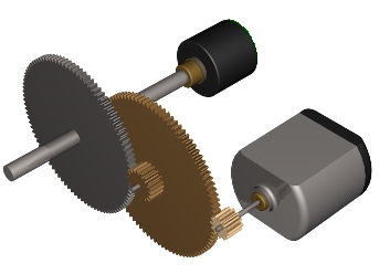
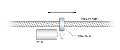
- Gear ratio (M:N) and/or the pitch of the linear screw (mm/rev).
- Rotary axes:
- For position in degrees PositionFactor is:PFAC = Pos_Units *(M/N)/360
- Linear axes:
- For position in milli-meters PositionFactor is:PFAC = Pos_Units)/MPITCH
See Motion Bus setup for pos_units and MPITCH setup
Step#5: Moving Direction
Positive direction of drive's position increments does not have to match the desired positive direction of user axis (Upwards, Left-Right, Counterclockwise). Therefore <axis>.direction flag is to be used:
<axis>.Direction = {1|-1}
Value of -1 indicates direction inversion.
Step#6: Velocity, Acceleration, Jerk units
Velocity units do not have to match position units (same for acceleration, jerk). User is free to select his/hers own units. For all the derivative units (velocity, acceleration, jerk) the default time scale is in milli-seconds, therefore scaling is needed.
To use position units per second for velocity one needs to define:
<axis>.VelocityFactor = <axis>.PositionFactor/1000
In this case if the user set the position in mm the velocity will be in mm/sec
To define velocity in RPM of the motor:
<axis>.VelocityFactor = Pos_Units /1000/60
For acceleration and jerk units is the same, their default values are expressed in velocity and acceleration units per milli-seconds. So in order to set them per seconds one needs to set them as:
    <axis>.AccelerationFactor = <axis>. VelocityFactor /1000
    <axis>.JerkFactor        = <axis>. AccelerationFactor /1000
Step#7:Units summary
Position, velocity, acceleration and jerk units are set by:
 <axis>.PositionFactor = …
 <axis>.Direction = …
 <axis>.VelocityFactor = ..
 <axis>.AccelerationFactor = ..
 <axis>.JerkFactor = …
Step#8:Position Limits
Setting position range of an axis. Setting max position:
<axis>.Pmax = … and enabling /disabling it: <axis>.PmaxEn = {0|1}
Setting min position:
<axis>.Pmin = … and enabling /disabling it: <axis>.PminEn = {0|1}
Setting the axis type:
<axis>.AxisType = 0 ‘ For linear axes
<axis>.AxisType = 1 ‘ For rotary axes
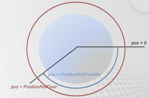
For rotary axes rollover can be defined: Enabling/Disabling it:
<axis>.PositionRollOverEnable = {0|1}
Setting the whole range:
<axis>. PositionRollOver
Setting the low value:
<axis>. PositionRollOverMin
Not that if the enable flag is not set the correspondent value does not need to be set.
Step#9: Motion Bus Units Setup
Depending on the type of Motion-Bus (EtherCAT, SERCOS, CanOpen) and drive used there are several parameters available for the user to be adjusted (not necessarily needed):
In case micro-interpolation is turned on in the drive, the velocity sent to drive must be properly scaled, this is done with (for counts per ms):
 <axis>.MotionBusVelocityScale = 0
 <axis>.MotionBusVelocityBase = 1
In case a limited drive’s position range is used (other then integer 32 bits):
 <axis>.CountMin = < drive min position value>
 <axis>.CountMax = < drive max position value>
Step#10: Motion Parameters
{{#invoke:Infobox|infobox}}
Motion parameters are grouped into velocity, acceleration and jerk values. They all have their max values for overall limitations, and their motion-default values that are used when motion is executed.
Velocity is set according to maximum axis physical limit (drives/motor capabilities and mechanical limitations):
<axis>.Vmax
Acceleration is set according to maximum axis physical limits (Max drive/motor current, axis load) in user units:
 <axis>.Amax
 <axis>.Dmax
Jerk is the third time-derivation of position, if smooth profiles are used it needs to be defined a good rule of thumb is to set J=BW*A, where J – jerk, A – acceleration, BW- control Bandwidth (Hz).
<axis>.JerkMax


