Element Coordination
Contents
- 1 Introduction
- 2 System Setup
- 3 New properties
- 4 Master-Slave Relationship
- 5 Affected(changed) commands
- 6 Moving Frame Coordinate Transformations
- 7 Algorithms and Software design
- 8 Examples
Introduction
The main goal of this feature is to synchronize both in space and in time movement of several robots together. This will be done using the standard master-slave relationship that exists in the system by expanding it into a general robot-to-robot connection. The feature that is going to be used is the Moving Frame Feature typically used in conveyor tracking.The source of the moving frame will be extended from simple axes list to any robot type cartesian command (SETPOINT, HERE).
The master robot is the master source of a moving frame that the slave robot follows. Same synchronization algorithms will be used except the issues related to the tracking window and triggering (these two will be irrelevant).
Relative movements of the slave robot during tracking are allowed and executed in the same way as in regular conveyor tracking.
The robot's mutual space-relationship will be defined through newly-added base and object location offsets of the moving frame. Together with it, mutual coordination of robots of different point types (world(robot) frame) and/or different NDOF's will be possible.
| IMPORTANT | |
| Only in case of robot's with same point-types the complete location will be used (position+orientation). In case of robots with different point-types only the positional part (X, Y, Z) of the master-robot location will be tracked. Orientation angles (Yaw, Pitch, Roll) will be ignored |
| IMPORTANT | |
| In case of robot's with same point-types user is able to select if tracking is done on position or orientation coordinates only or on both of them. See MovingFrame.type property |
| NOTE | |
| Axes' position limits and acceleration/velocity thresholds are checked (monitored) during tracking in the same way as in regular conveyor tracking |
| DANGER | |
| It is important to emphasize that this feature (Element Coordination using robot-based Moving Frame) does not prevent robot collisions. Robot collision prevention is completely out of this topic. |
System Setup
Data Creation
There are two kinds of Moving Frame (MF) objects in the aico.control system: axis-based and robot-based.
Both of them are created in the same way as axes-based means using the command:
The difference between axes-based and robot-based moving frames is in the argument supplied to the MasterSource command. In axis-based MF's only axes as master sources are used. Also,in the axis-based MF's the point-type of all location-MF's properties (Zero, Here, Upstream, DownStream) are same as point type of the MF (i.e. <mf-type>).
In robot-based MF's master-source is a robot element with it's own point-type. In robot-based MF's the relation between MF's locations and the robot's locations will be defined using the newly introduced properties. (See: Translation Transformation )
Master Source
<Moving Frame>.MasterSource property will allow adding robot element's command (setpoint) or feedback(here) locations as masters, the following sytnax will be valid:
<Moving Frame>.MasterSource = <robot>.setpoint and <Moving Frame>.MasterSource = <robot>.here
| NOTE | |
| The point-type of the master <robot> does not have to match the point-type of the <moving frame>! However the type of the <moving frame> and the slave robot must match! |
MF.TYPE
Assigning master robot's locations to the master-source automatically imposes certain relationship between the positions and orientations of the MF and the master-robot. The following table explains the relationships between master's and slaves' point types and the <MF>.type values.
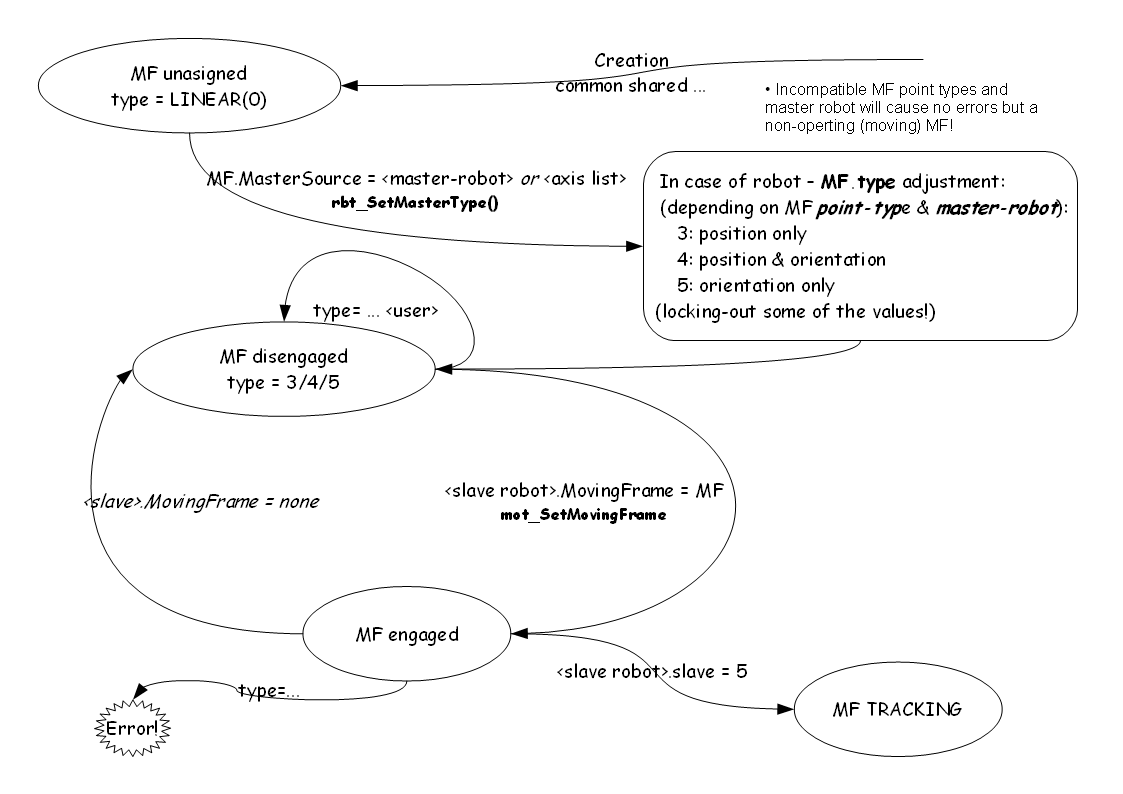
→ Setting the MasterSource to the one of the master robot locations(SetPoint or Here) will automatically change the Moving-Frame type to its default value (see the table) and lock it. Locking means that according to the given MasterSource only certain MF.type values are allowed (those with "✓" sign in the table). And if the user tries to assign any other value an error will be returned.
| <mf>.type value | axis-MF | robot-MF pointtype(position)robot = robot-MF pointtype(position)MF or: pointtype(orientation)robot = robot-MF pointtype(orientation)MF |
robot-MF neither position or orientation match |
| 0 (linear) | ✓(default) | invalid | invalid |
| 1 (rotary) | ✓ | invalid | invalid |
| 2 (rotary de-coupled) | ✓ | invalid | invalid |
| 3 (position only) | N/A | ✓ | ✓ (default) |
| 4 (orientation only) | N/A | ✓ | invalid |
| 5 (both pos. and ori.) | N/A | ✓ (default) | invalid |
Type-assignment table for some of the most used point-types
| master-robot | ||||||||
| MF | X | XY | XYZ | XYZR | XYZYPR | YPR | YP | |
| X | p | p | p | p | p | p | p | |
| XY | p | p | p | p | p | p | p | |
| XYZ | p | p | p | p | p | p | p | |
| XYZR | p | p | p | p/o/po | p | p | p | |
| XYZYPR | p | p | p | p | p/o/po | o | p (inactive) | |
| YPR | p (inactive) |
p (inactive) |
p (inactive) |
p (inactive) |
o | o | p (inactive) | |
| YP | p (inactive) |
p (inactive) |
p (inactive) |
p (inactive) |
p (inactive) |
p (inactive) |
o | |
- p(3) position only
- o(4) orientation only
- po(5) both position and orientation
| NOTE | |
| In case of pure orientational moving frames driven by inadequate master-robot point type, type will be set to position (3) but the acutall moving frame will be inactive (can not move) |
Example 1
common shared MF as moving frame of XYZR
MF.mastersource = SCARA.setpoint
Sets MF.type automatically to 5 (both position and orientation - default value)!
Trying to change it to a value not supported by the master (e.g. MF.type = 0 ) source will return error:
Example 2
common shared MF as moving frame of XYZR
common shared gXYZ   as group axnm = a1 axnm = a2 axnm = a3 model=1  of XYZ
MF.mastersource = gXYZ.setpoint
In this case we have situation of same position type but a different (or non-existing) orientation type. The MF.type automatically to 3 (position only)!
Example 3
common shared MF as moving frame of XYZYPR
common shared TILT   as group axnm = a1 axnm = a2 axnm = a3 model=1  of YPR
MF.mastersource = TILT.setpoint
In this case we have situation of same orientation type but a different (or non-existing) position type. The MF.type automatically to 4 (orientation only)!
Example 4
common shared MF as moving frame of XYZ
common shared TILT   as group axnm = a1 axnm = a2 axnm = a3 model=1  of YPR
MF.mastersource = TILT.setpoint
In this case we have situation that both point types do not have anything in common ! So, type will be set to 3 (position only) automatically.
New properties
Moving Frame Base Offset
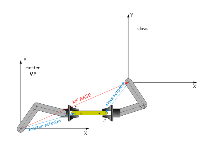
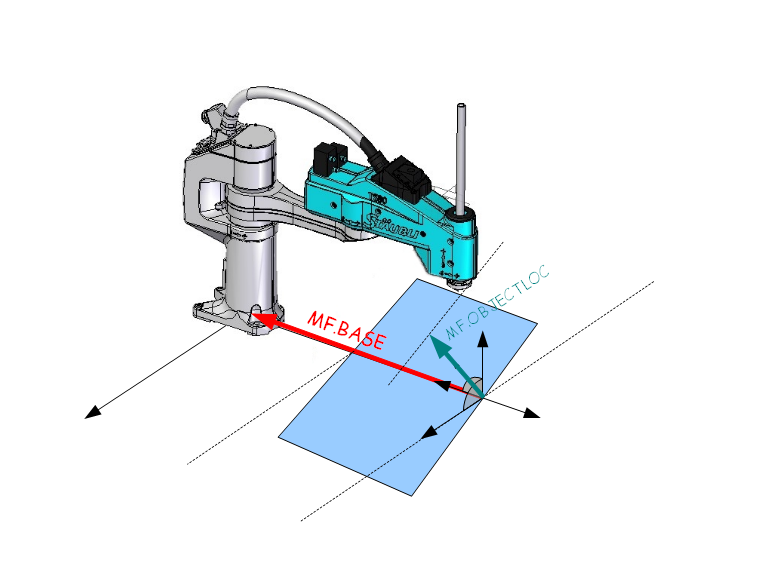
Mutual space-relationship (position and orientation) between master and slave robots is described by BASE property of MF.
- <moving-frame>.BASE is an offset of the master robot to the slave. It is a moving-frame's property.
Object Location
Object moved by two robots or the relative position of two robot's end-points to each other is described by <moving-frame>.OBJECTLOC Moving-Frame property. It describes the relative position and orientation of the slave's setpoint from the actual master's source coordinates (SetPoint or Here). It holds the same point-type as the parent MF (or the slave-robot).
See Also: Object Location Property
| NOTE | |
| OBJECTLOC can be used for updating new point-of-contact position in consecutive pick&place applications similar as TRIGGER command in axis-based MF's |
Master-Slave Relationship
Once the MF parameters are set the connection between master and slave positions is defined by the following formula.
slave.robot = MS2MF( MF.base-1 : MF.MSource:MF.ObjectLoc )
where MF.MSource is either <master>.setpoint or <master>.feedback
MS2MF function is defined as:
Master Source to Master Frame function: A = MS2MF(B) is defined as:
A->position = p-projection (B->position)
A->orientation = B->orientation (for MF.types: 4 and 5 only!)
- p-projection is simple matrix multiplication in the form: A->position = TranslationTransformation * B->position
Point Type transformation
Translation Transformation
Contrary to the ordinary axes-MFs robot-MFs can have different point type than the slaved robot. In order to translate location from MF point type into slave-robot point type <moving-frame>.TranslationTransformation 3x3 double matrix property is defined.
- defines a transformation-matrix for of the translation (position) part from MF.MasterSource's point-type to the MF's robot-type.
- the matrix dimension is automatically adjusted by position dimension of MF and the master robot.
| Master-Source: XY | Master-Source: XYZ | |
| MF-type: XY | TranslationTransformation[1-2][1-2] | TranslationTransformation[1-2][1-3] |
| MF-type: XYZ | TranslationTransformation[1-2][1-3] | TranslationTransformation[1-3][1-3] |
for example, defining:
common shared MF as moving frame of XYZYPR
MF.MasterSource = GXY
automatically defines:
TranslationTransformation[*][*] =
or: TranslationTransformation is 2x3 matrix!
| NOTE | |
| In case when number of position coordinates of MF is less then of MasterSource the remaining coordinate will be assigned by the MF.BASE corresponding coordinate value. |
Affected(changed) commands
Activation(Syncing)
Setting <robot>.slave = 5 immediately enters into synchronization-tracking mode, no trigger command is needed.
As the working window in case of robot-based MF's does not exist the MF.ZERO will return the current MF position at the moment of entering "slave=5"! After that moment the slave robot will try to synchronize to the Moving Frame Location: MovingFrame(t) = MF(t) - MF(t0)
where t0 is the moment of issuing "slave=5" (See:Absolute_Movements_During_Conveyor_Tracking)
Where the MF(.) is:
MF(t) = MS2MF( MF.base-1 : Master(t):MF.ObjectLoc )
Master(t) - position of robot master axis at moment t.
MS2MF defined in: Master Source to Moving Frame function
The relation to MC-Basic language variables is obvious:
<mf>.here = MF(t)
<mf>.zero = MF(0) (See MovingFrame.ZERO)
This means that the total slave robot motion of the slave robot that began to track (slave=5, synced or not) is the SAME as position of free slave robot (slave=0) IF the master robot did not move. In other words, if you want to teach some points on a moving object connected to the master robot just stop the master robot and move the slave to it's desired destination on the object.
| NOTE | |
| Movement to MF.ZERO after initialization of tracking causes the slave robot to synchronize exactly to the master robot's location. |
Deactivation(DeSyncing)
Setting <robot>.slave = 0 immediately enters into de-synchronization mode, which smoothly reduces tracking velocity to zero. (The part of the velocity induced by tracking not the velocity of added movements).
| NOTE | |
In robot-based MF's de-syncing is done using initial values of the movement in cartesain space (position, velocity, acceleration) using the parameters below:
It is possible to activated syncing to another robot or just a plane movement during de-syncing. (Same as axes-based MF's) |
Is Moving Frame Synchronized
The Is-Moving-Frame-Synchronized flag will have the same function as in axis-based MF's.
Tracking Parameters
The parameters:
- VelocityMaxTrans, VelocityMaxRot, AccelerationMaxTrans, AccelerationMaxRot, JerkMaxTrans, JerkMaxRot
- Dampingfactor, FilterFactor, MaxFlops
will be used in the same way as in axis-based MF's. Instead of acting on a scalar distance() between master axis and tracking variable, cartesian distance () and Euler's angle distance () between master robot position and slave-robot master tracking variable will be used for building criteria of stressful synchronization.
Trigger
As in robot-based MF's the concept of working-window and entering an object into it does not exist, the Trigger command will have no effect on robot-based moving frames. The actual moment of tracking will start always with setting of slave=5 independently of previously used trigger command.
NOI
In case of MF-robot NOI will return always -1.
Is In Window
Is In Window flag will return always 1 (true), actually there is no concept of working windows in this type of MF.
Unused Moving-Frame properties
- Upstream, Downstream, Upmaster, Downmaster
As the working-window concept does not exist in robot-based MF's these properties will have absolutely no influence on MF-robot operation.
Next Item command
- NEXTITEM command will have no effects on MF-robot operation.
Moving Frame Coordinate Transformations
Slave robot is connected to a master through Moving-Frame assigned to the slave's master frame property:
<slaverobot>.MasterFrame = <master frame>
Master frame is a link between slave and master robot. It Includes definition of the master-source which can be either robot Cartesian command point (SETPOINT) or robot's Cartesian feedback (HERE):
<master frame>.MasterSource = <masterrobot>.SETPOINT
BASE transformation
Master frame defines spacial relationship (distance and rotation) of the slave's robot frame to the master: <Master Frame>.Base
Defining an Object
In total the object is held by two robots from two sides. Looking from the master's coordinate frame we have two points (in master-robot's world(robot) frame):
<masterrobot>.setpoint
<masterrobot>.setpoint:<movingframe>.objectloc
The second point of the object can be also reached through salve robot by (viewed by master-robot's world(robot) frame):
<movingframe>.base:<slaverobot>.setpoint
<Moving Frame>.ObjectLoc is location property of the Moving Frame data-object of the same point-type as the moving frame. For example, it means if the moving frame was declared as XYZR (common shared MF as moving frame of XYZR), the OBJECTLOC will be also location of XYZR type.
The OBJECTLOC specifies position and orientation of the slave's end-effector relative to the master's end point (Master Frame actually).
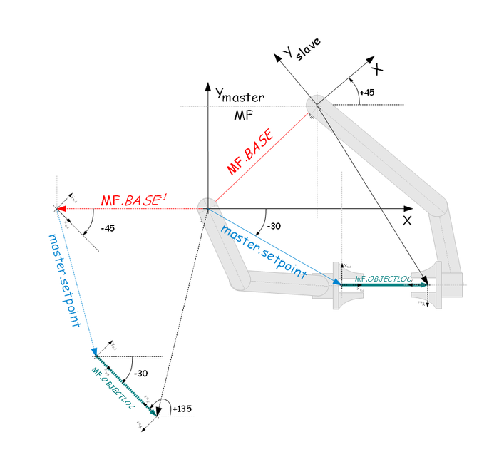
Example of complete slave command calculation
mf.base = #{100,100,0,45}
mf.base-1 = #{-141,100,0,-45}
mf.objectloc = #{80,0,0,180}
master.setpoint = #{130,-72,0,0}
slave.setpoint = mf.base-1:master.setpoint:mf.objectloc
slave.setpoint = #{-43 , -200 , 0 ,135 }
- The above calculations are true in case both robots are of same (XYZR) point-type and the default MF.type value (5- both position and orientation) is used.
Example of three robots working on a same object
Here is an example of three-robot cooperation. One robot is defined as a master and the other two are slaves. Each of the slave robots is connected through it's master frame to the master robot on different distances from it and on different gripper-points on the object.
Frame Calculation in three-robot case
In this example we will define two Moving frame with each of them having a different OBJECTLOC.
The first Moving Frame:
Common Shared MF1 As Moving Frame Of XYZR
MF1.MasterSource = <masterrobot>.SETPOINT
MF1.BASE = #{..., ..., ..., 0}
MF1.OBJECTLOC = #{L,..., ..., 180}
The second Moving Frame:
Common Shared MF2 As Moving Frame Of XYZR
MF2.MasterSource = <masterrobot>.SETPOINT
MF2.BASE = #{..., ..., ..., 0}
MF2.OBJECTLOC = #{SQRT(3)*L,L/2, ..., -150}
- Assuming the object is even-sided (Equilateral) triangle of the side length L.
| NOTE | |
| The orientational part of the second object-location MF's it is -150 degrees. The first slave's robot Xtool axis is in exactly opposite direction to the master's Xtool axis. And the second slave robot's Ytool axis is in exactly opposite direction to the master's Ytool axis. |
Algorithms and Software design
- The master slave relationship is based on the same principleas in robot-based MF's as in axis-based MF's. The underling idea is to have same sort of movement if the MF is standing or moving.The principals are described here: Absolute_Movements_During_Conveyor_Tracking
- Axis-based moving frame tracking algorithm based on predicting the rendezvous point and limiting the motion by velocity, acceleration and jerk constant is described here: One_Dimensional_Tracking_Algorithm
- Same algorithm (tracking) applied on 3-dimensional position vector (Euler angles) is explained here: Position_Tracking_Algorithm
- Same algorithm (tracking) applied on 3-dimensional orientation vector is explained here: Orientation_Tracking_Algorithm
- Concept of global frame coordinate system as addition to base and world(robot) frames for multiple robot usage is described here:Global Coordinates
- Enlargement of axis-based MF data structures is shown here: Software_Design
Issues List:
Issue 5954![]()
Issue 5955![]()
Issue 5957![]()
Issue 5960![]()
Issue 5963![]()
Issue 6058![]()
Issue 6075![]()
Examples
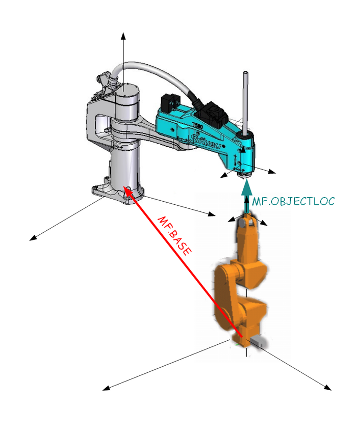
Example 1. two different robot kinematics
Cooperation between two unequal robot kinematics.
Moving Frame definition:
Common Shared MF as Moving Frame of XYZR
Linking it to the source (master):
MF.MasterSource = Puma.Setpoint
The master-source is a robot(PUMA) of point-type XYZYPR and the linked robot(SCARA) or the MF is of XYZR point type. In this case the MF.type will be automatically set to 3 (position only). Orientation angle changes of the master robot will have no effects on the slave. So we need to define transformation matrix:
Or in the code:
' First column:
MF.TranslationTransformation[1][1]=1
MF.TranslationTransformation[2][1]=0
MF.TranslationTransformation[3][1]=0
' Second column:
MF.TranslationTransformation[1][2]=0
MF.TranslationTransformation[2][2]=1
MF.TranslationTransformation[3][2]=0
' Third column:
MF.TranslationTransformation[1][3]=0
MF.TranslationTransformation[2][3]=0
MF.TranslationTransformation[3][3]=1
And then the offsets definitions:
The XY coordinates will be offseted for (10,10) mm:
MF.base = #{10,10,0,0}
A distance of 100mm between the two robots tool-tips is defined as:
MF.ObjectLoc = #{0,0,100,0}
and the tracking (master-slave) is defined by:
Scara.Masterframe = MF
and started:
Scara.slave = 5
Example 2. SCARA and a tilting table
Moving Frame definition :
Common Shared MF as Moving Frame of XYZR
Having a tilt table robot (Object Having only Yaw and Pitch angle):
Common Shared TiltTable As Group Axnm = Ax5 Axnm = Ax6 Model = 1 of YP
Linking it to the source (master):
MF.MasterSource = TilTable.Setpoint
The master-source is a tilt-table of point-type YP and the linked robot or the MF is of XYZR point type. The MF.type will be automatically set to 3 (position only).
Transformation matrix for position actually does not exist as the TiltTable have no position component! So there is nothing to be set here.
And then the offsets definitions:
The XY coordinates will be offseted for 200 mm:
MF.base = #{-200,0,0,0}
Defining the object-location of 100mm makes the trick!
mf.base = #{Xb,Yb,Zb,Rb}
mf.objectloc = #{Xo,Yo,Zo,0}
master.setpoint = #{yaw,pitch}
slave.setpoint = mf.base-1:master.setpoint:mf.objectloc
i.e. the vector [Xo,Yo,Zo] will be rotated by the tilt-table angles [yaw,pitch]!!!
and the tracking (master-slave) is defined by:
Scara.Masterframe = MF
and started:
Scara.slave = 5
Example 3. Two SCARA's working on a same piece
A robot to robot tracking example:
Two SCARA robots, one master the other is slave.
Case of tracking with two SCARA robots.
Setup:
set the slave robot to track the master on a distance of 100mm pointing in face-to face direction (180º)
Common Shared MF as Moving Frame Of XYZR
MF.MasterSource = ScaraMaster
MF.ObjectLoc = #{100,0,0,180}
ScaraSlave.MovingFrame = MF
ScaraSlave.Slave=5
At the moment of engagement (i.e. Slave=5) Zero point is recorded!
Wait to be Synchronized and arriving to master-position together:
System waits until MF is synchronized (Is-Moving-Frame-Synchronized equals 1) and motion towards Zero point is completed (isMoving flag is not positive)
Moves MF.Zero
While ScaraSlave.IMFS <> 1 and ScaraSlave.Ismoving > 0
Sleep 1
End While
Do something, or just stay in tracking mode.
Stopping.De-Synchronize:
slave = 0
while  ScaraSlave.IMFS <> 0
Sleep 1
End While
After this ScaraSlave will be stopped not exactly on the ScaraMaster's path (deviation is more or less random and depends on the master's robot path and joints' deceleration parameters).
Example 4. Coordination
Relative position between the robots during tracking, the slave robot to track the master on a distance of 100mm pointing in face-to face direction (180º)
Coordination. zoomed detail: Coordination detail
Example 5. PUMA and SCARA on a patch placement job
For setting up global; coordinates see: Global_Coordinates
Detail view of work-space locations
Geometry
Also see: Global_Coordinates
the given setup can be accomplished in four different ways:
| World(Robot) Frame | Base Frame | Global Base | Moving Frame |
|
puma.base = #{0,0,0,0,0,0} |
puma.base = #{200,100,0,0,0,0} |
puma.base = #{200,100,0,0,0,0} |
puma.base = #{200,100,0,0,0,0} |
| NOTE | |
| All four given code examples will bring the two robots to same positions! |
| IMPORTANT | |
| The "Moving Frame" example takes into account SCARA base coordinates and not the global ones as the MF is declared of XYZR point type. |
System setup
definitions:
Common Shared MF As Moving Frame Of XYZR
Common Shared hold As Location Of XYZR
Common Shared patch_feeder As Location Of XYZR
initialization :
SCARA.Base  = #{100,100,0,0}
SCARA.GBASE = #{0,100,700,0,0,0}
PUMA.Base   = #{200,100,0,0}


MF.MasterSource = PUMA.SETPOINT
MF.ObjectLoc    = #{0,0,50,0}
MF.Base         = #{200,0,-700,0}

SCARA.BlendingMethod = 2
SCARA.BlendingFactor = 80
SCARA.MasterFrame = MF
Execution code:
while patches()
   MoveS PUMA MoldPose((PatchNumber()))
   MoveS SCARA patch_feeder
   MoveS SCARA down
   Call TakePatch(SCARA)
   Moves SCARA up
   Moves SCARA hold
   MF.ObjectLoc = MoldProfile(PatchNumber())
   SCARA.slave = 5
   Moves SCARA MF.Zero
   Call GluePatch(SCARA)
   Moves SCARA up
   SCARA.Slave = 0
   Moves SCARA hold
end while
Functions and variables used in the program above:
Function MoldPose( n as long) as location of XYZYPR
Function returning pathc position on the mold in PUMA's coordinate system (e.g. XYZYPR)
Function MoldProfile( n as long) as location of XYZR
Function returning the shape profile of the mold in XYZ coordinates , setting it into OBJECTLOC will effectively set a right position of the SCARA robot on the mold. Returns SCARA locations (XYZR).
Sub TakePatch(robot as generic group)
Subroutine for taking (gripper manipulation, vacuum, waiting, etc) a patch from the feeder.
Sub GluePatch(robot as generic group)
Subroutine for placing the patch on the mold. Here included are all synchronizations needed (wait, gripper open, ...)
MF.Base
Moving Frame Base offset,
hold
Waiting position
Patch_feeder
Position from where the patches are taken.
