Teach Pendant Operation Guide
Contents
Overview
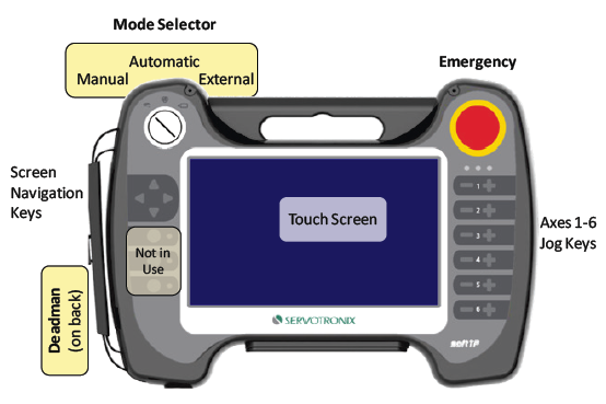
The softTP is a teach pendant (TP) designed for use with softMC 3 and softMC 7 motion controllers and various types of robots, such as SCARA, PUMA and Delta. The softTP allows operators to move the robot by means of jog keys, and to create and run complete robot programs written in MC-Basic.
The softTP touch screen interface enables quick and easy application development. The softTP software package also includes a full-featured emulator running on Windows/Linux.
Access Permission Levels
The softTP has four different user levels.
- Viewer
- Operator
- Programmer
- Administrator (not shown)
Each softTP user must login with a password for a specific permission level.
The following table indicates the functions available to each user level.
| Viewer | Operator | Programmer | |
|---|---|---|---|
|
View main robot data. |
|
|
|
|
Switch between TP screens. |
|
|
|
|
View the status of digital IOs and error history. |
|
|
|
|
View data (variables). |
|
|
|
|
View programs. |
|
|
|
|
Start/stop certain processes (e.g., jog) |
|
|
|
|
Start/stop certain programs. |
|
|
|
|
Modify data (variables). |
|
|
|
|
Load, run and debug programs. |
|
|
|
|
Acknowledge errors. |
|
|
|
|
Enable the robot. |
|
|
|
|
Create and edit user programs (UPG/ULB). |
|
|
|
|
Create and edit (teach) program variables. |
|
|
|
softTP Switches
Deadman Switch
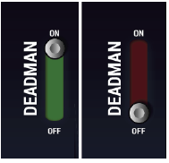
The deadman switch is located on the back of the softTP. The switch has three positions: released, partially pressed, and fully pressed.
Motion and jogging commands can be issued from the softTP only when the teach pendent is in Manual mode, and the deadman switch is in the intermediate, partially-pressed position.
If the deadman switch is released, or fully pressed, while axes are in motion, the motion stops immediately.
The deadman can switched ON (partially pressed position) only from fully released position, not from fully pressed position.
|
Deadman |
|
|
Deadman |
|
|
Deadman |
|
When using TP Emulator, the deadman switch status is represented by the on‑off vertical switch on the left side of the screen.
Emergency Stop
Note: The Emergency Stop switch must be connected to the STO circuit.
Pressing the Emergency switch automatically powers off the motors, stops motion and and disables the axes.
Mode Selector Switch
The Mode Selector switch on the front of softTP has three positions: Manual, Automatic and External.
If the mode setting is switched from Automatic to Manual or External while a user program is running, program execution and the current motion stop immediately .
|
Mode |
Description |
|
Manual |
|
|
Automatic |
|
|
External |
|
When using TP Emulator, the mode switch status is represented by the horizontal switch on the top left of the screen.
Interface Elements
Toolbar
| |
Toolbar |
Description |
|
Logout |
Exits the TP interface. | |
|
TP Operation Mode |
Indicates the teach pendant’s current operation control mode, as defined by the mode selector switch. In the TP Emulator, the three positions are marked M, A and E. | |
|
Message box |
Message field for system notifications. Locatedin the center of the screen. | |
|
Axes in Motion |
Indicates state of the axes: | |
|
Primary TP |
Indicates that the teach pendant in use is the primary TP. If another TP is connected, this indicator will be off. (Not currently implemented) | |
|
Collapse/Expand |
Hides/shows the menu bar, to provide additional screen space. | |
|
Enable | Disable |
Enables and disables all axes, and indicates the state of the axes. |
Menu Bar
The menu bar provides access to the softTP screens.
|
Screen |
Function' |
|
Jog |
|
|
Program |
Used to create, edit, run and debug MC‑Basic programs. |
|
Data |
Used to add and edit variables attached to the selected domain. |
|
IO |
Used to monitor and switch system digital inputs and outputs. |
|
Diagnostics |
Displays motion bus settings and status of configured axes and devices. |
|
Errors |
Displays the log of faults in the softMC motion controller. Also used to acknowledge and clear faults. |
|
Settings |
Displays system software components and versions. |
Jog Keys
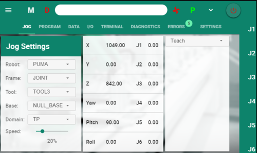
When Frame is set to Joint, keys are labeled according to axes: J1, J2, J3, and so on.
When Frame is set to Base, Tool or World, keys are labeled according to Cartesian coordinates: X, X, Z, Yaw, Pitch, Roll.
Domains
Domains serve to separate data from programs, thereby allowing manipulation of program data (variables) without affecting program code.
Every program is associated with a domain. In MC-Basic, domains are implemented by a namespace feature of the MC-Basic language. (Refer to: http://softmc.servotronix.com/wiki/Namespace).
All variables of a given domain are automatically saved to a separate file on the softMC disk after they are created or updated.
The softTP provides three system domains for certain data, which do not have associated program files: TP, Base and Tool.
Whenever a project is created from the softTP, an associated domain with the same name as the project is generated, and the softTP automatically switches to this domain.
TP Domain
TP variables are not assigned to a particular project or program.
They can be used freely as auxiliary variables for debugging and other functions.
Base Domain
Base variables are not assigned to any program and are used to store the base property values used by the selected robot.
It is recommended that variables in this domain use the naming format BASE1, BASE2, and so on.
Tool Domain
Tool variables are not assigned to any program and are used to store the tool property values used by the selected robot.
It is recommended that variables in this domain use the naming format TOOL1, TOOL2, and so on.
Jog Screen
The Jog screen is the main screen for working with the robot.
- It displays the current robot joint and Cartesian coordinates.
- It enables user to teach/set new points, move(s) to a predefined point.
- It provides tool calibration and align functionality.
Frames
softTP supports five jog frames: Joint, Base, Tool, World XYZ,and World ZYZ.
- Joint frame is used for jogging the individual robot axes: J1 … J6.
- Base, Tool and World frames represent Cartesian frames. When one of these frames is selected, jogging is in XYZ coordinates and in the corresponding orientation axes:
- Base and Tool frames allow jogging of X, Y, Z, Yaw, Pitch and Roll.
- Note that the default Euler-Angle representation of Yaw-Pitch-Roll is a ZYZ rotation sequence only.
- World frame has two modes: ZYZ and XYZ.
- ZYZ is the default mode; it has standard orientation angles as Yaw-Pitch-Roll of a ZYZ rotation sequence.
- XYZ is an alternative mode; it has non-standard orientation angles as Rx-Ry-Rz of an XYZ rotation sequence.
- In MC-Basic, Base, Tool and World frames are considered location data types.
A Cartesian robot frame (for PUMA robot) is a 6-dimensional Cartesian coordinate system in which the robot tool tip position and orientation are defined.
For a PUMA robot both Base and Rtool frames are in the form X-Y-Z-Yaw-Pitch-Roll.
The Frame option in the Jog screen allows you to select a different frame for jogging in. You can set different frame parameters (values) in various ways; for example:
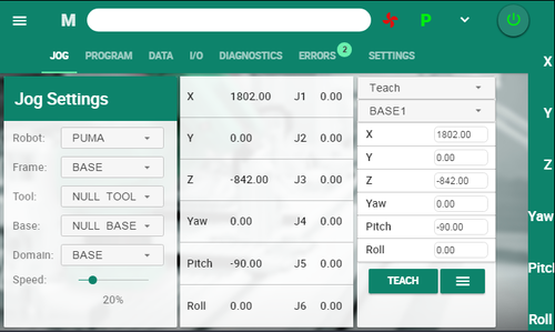
- By using Teach option to teach them directly – this is commonly done for Base.
- By using Tool Calibration options – this is commonly done for Tool.
Teaching Points
Positions are taught in the Jog screen, and defined in either Joint or Cartesian coordinates.
Before teaching a point, you must first create a Location or a Joints position in the Data screen. Be sure the position is attached to the appropriate Domain.
In the Jog screen, make sure Domain and Frame are set accordingly.
Use the Teach button to set position coordinates automatically, or enter position values manually.
|
Setting |
Description |
|
Robot |
The specific type of robot or axis for movement or position teaching. |
|
Frame |
Cartesian (Tool, Base and World): Linear movement along X, Y and Z directions, angular motion around a statuc X, Y and Z coordinates. |
|
Tool |
Used for selecting the actual tool:
|
|
Base |
Used for selecting the actual base:
|
|
Domain |
Used for selecting the domain:
|
|
Speed |
Slider to increase/decrease the jogging speed, as a percentage of the maximum speed. |
|
X Y Z Yaw (Rx) Pitch (Ry) Roll (Rz) |
Displays the Cartesian coordinates of the robot even when operating in Joint mode. |
|
Teach |
Used to define the values (Joint or Cartesian) to be taught. Enter position values manually, or press Teach. |
|
Move |
Generates joint interpolated motion to the specified target |
|
Moves |
Generates Cartesian interpolated motion (straight line) to the specified target. |
|
Tool Align |
Aligns the Tool X, Y or Z direction with the nearest World axis, while the tool tip remains in position |
|
Tool Calibrate |
Two methods for calibrating the tool:
|
Program Screen
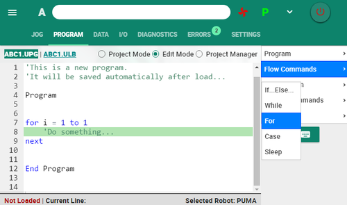
The Program screen is used for creating, editing, running and debugging MC‑Basic programs.
The file extensions *.UPG user programs and *.ULB for user libraries are used to distinguish user programs from general system programs and settings.
- Administrator level users can access and manipulate both global (*.PRG/*.LIB) and user (*.UPG/*.ULB) programs and libraries.
- Programmer level users can create/edit/run/debug user programs only (*.UPG) and user libraries only (*.ULB).
- Operator level users can run/debug user programs only (*.UPG) and user libraries only (*.ULB).
- Viewer level users have no access rights to user programs (*.UPG) and user libraries (*.ULB).
A project comprises set of files with the same names but different extensions (e.g. TASK.UPG, TASK.ULB, TASK.DEF and TASK.VAR). The files are generated when a Programmer level user creates a project.
Only files with the extension UPG and ULB are visible to non-Admin users:
- name.UPG: The main user task.
- name.ULB: The library containing the functions and subroutines used in the main user task.
Project Mode
| Setting | Description |
|---|---|
|
Open Project |
Opens an existing project. |
|
New Project |
Opens a new project. When prompted for a name, enter up to 8 characters. Valid characters are a-z, A-Z, 0-9, _ (underscore), - (hyphen). When a new project is created, a user program, a user library, and a domain of the same name are also created. |
|
Load |
Loads a program and associated library from the softMC flash memory to the softMC RAM so that the program can be executed. |
|
Unload |
Unloads a program/library from the softMC RAM so that they can be edited. |
|
Kill |
Aborts execution of a running program. |
|
Idle |
Stops the program at the end of the line currently being executed. Robot motion is also stopped. |
|
Run |
Starts execution or continues execution (if idle) of the program and motion. |
|
Jump to Line |
Jump to a line in current program. |
|
Step Over |
Skip over the subroutine. |
|
Step Into |
Step into the subroutine. |
|
Step Out |
Exit the subroutine. |
Edit Mode
Provides the code syntax for commonly used instructions, including prompts for the data required for completing the code line/s.
| Setting | Description |
|---|---|
|
Program |
Instructions for defining subroutines and functions.
|
|
Flow Commands |
Instructions used to change the flow of a program based on specific conditions.
|
|
Interpolation |
|
|
Motion Commands |
|
|
I/O |
|
Project Manager
| Setting | Description |
|---|---|
|
[Project list] |
|
|
Delete |
Deletes selected project. |
|
Save As |
Saves a copy of current project using a new name. |
|
Rename |
Renames the current project. |
Data Screen
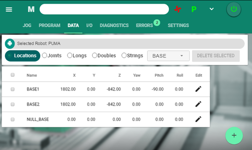
The Data screen is used for creating and editing variables in the domain that is currently selected.
Variables can be robot positions or any other data typesupported in MC‑Basic, such as long, double and string.
Select the domain, and the type of variable, then click the + button to create a variable.
A dialog box opens according to type of variable.
Enter values.
|
Setting |
Description |
|
Locations |
World/Cartesian positions. |
|
Joints |
Joint positions. |
|
Longs |
Numeric variable: 32-bit integer. |
|
Doubles |
Numeric variable: 64-bit floating point. |
|
Strings |
ASCII or UTF-8 string. Length is unlimited. |
|
Domain |
Either a system domain (TP, Base, Tool) or a user-defined project domain. |
I/O Screen
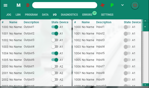
Allows monitoring of the system inputs and outputs, and toggling of outputs.
IO names are defined in DAT files (TPIN.DAT and TPOUT.DAT).
This screen is updated in realtime.
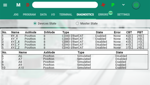
Diagnostics Screen
Two views. Devices and Master.
Shows status and properties of the devices and the motion bus in the system.
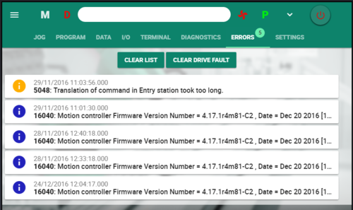
Errors Screen
When errors occur, an icon is displayed in the menu bar, and indicates the total number of errors.
- Clear List – removes all errors from the list
- Clear Drive Fault – removes all errors from the softMC
Different icon colors indicate the severity of the error or the type of message.
- Yellow: Note
- Blue: Info
- Red: Error
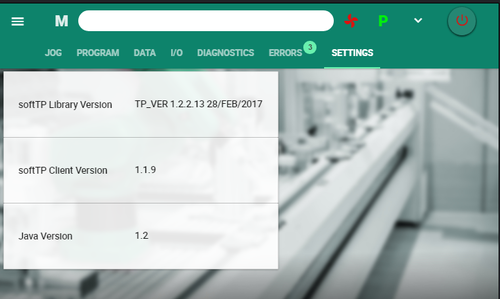
Settings Screen
Shows version information of software components.
Additional information is visible to Administrators.
|
Setting |
Description |
|
TP Library Version |
Displays the version of the currently loaded set of TP library files. |
|
softTP Client Version |
Displays the version of the softTP user interface software. |
|
Java Version |
Displays the version of the Java software in use. |
