Difference between revisions of "Work Space Limits"
m (→Example) |
(→Example: new example) |
||
| Line 81: | Line 81: | ||
| − | == | + | ==Examples== |
| − | {| border="1" cellpadding="5" cellspacing="0" | + | |
| + | ==6 Degree Of Freedom (DOF) Robot== | ||
| + | |||
| + | {| border="1" cellpadding="5" cellspacing="0" style="text-align: center" | ||
!width = "100" bgcolor = A9A9A9| '''Frame''' | !width = "100" bgcolor = A9A9A9| '''Frame''' | ||
| Line 128: | Line 131: | ||
| − | Assume that the desired SetPoint is: #{100,100,0,0,0,0} and that P<sub>b</sub> | + | Assume that the desired SetPoint is: #{100,100,0,0,0,0} and that P<sub>b,0</sub> is: #{100,100,900,-45,90,0} - '''Is it in the work area of the limits?''' |
| − | {| border="1" cellpadding="2" cellspacing="0" | + | {| border="1" cellpadding="2" cellspacing="0" style="text-align: center" |
!width = "100" bgcolor = A9A9A9| '''Frame''' | !width = "100" bgcolor = A9A9A9| '''Frame''' | ||
| Line 166: | Line 169: | ||
|World | |World | ||
|CheckPoint = MachineTable:WorkPiece:SetPoint = #{420,70,50,0,90,-90} | |CheckPoint = MachineTable:WorkPiece:SetPoint = #{420,70,50,0,90,-90} | ||
| + | |'''Yes''' | ||
| + | |||
| + | |} | ||
| + | |||
| + | |||
| + | ==4 Degree Of Freedom (DOF) Robot== | ||
| + | |||
| + | {| border="1" cellpadding="5" cellspacing="0" style="text-align: center" | ||
| + | |||
| + | !width = "100" bgcolor = A9A9A9| '''Frame''' | ||
| + | !width = "250" bgcolor = A9A9A9| '''Value''' | ||
| + | !width = "100" bgcolor = A9A9A9| '''Xmin, Xmax''' | ||
| + | !width = "100" bgcolor = A9A9A9| '''Ymin, Ymax''' | ||
| + | !width = "100" bgcolor = A9A9A9| '''Zmin, Zmax''' | ||
| + | |||
| + | |- | ||
| + | |WorkPiece | ||
| + | |#{20, 100, 100, 0} | ||
| + | | -100, 250 | ||
| + | | -300, 30 | ||
| + | | -200, 200 | ||
| + | |||
| + | |- | ||
| + | |MachineTable | ||
| + | |#{120, 60, 0, 0} | ||
| + | | 0, 700 | ||
| + | | 0, 500 | ||
| + | | 0, 500 | ||
| + | |||
| + | |- | ||
| + | |Base | ||
| + | |#{0, 0, 0, 0} | ||
| + | | -1000, 1000 | ||
| + | | -1000, 1000 | ||
| + | | 0, 1000 | ||
| + | |||
| + | |- | ||
| + | |Tool | ||
| + | |#{0, 20, 40, 10} | ||
| + | | -30, 20 | ||
| + | | -30, 20 | ||
| + | | -30, 20 | ||
| + | |||
| + | |- | ||
| + | |World | ||
| + | |None | ||
| + | | -1500, 1500 | ||
| + | | -1500, 1500 | ||
| + | | 0, 2000 | ||
| + | |||
| + | |} | ||
| + | |||
| + | |||
| + | Assume that the desired SetPoint is: #{660, -140, -60, 0} and that P<sub>b,0</sub> is: #{780, -100, -100, 0} - '''Is it in the work area of the limits?''' | ||
| + | |||
| + | |||
| + | |||
| + | {| border="1" cellpadding="2" cellspacing="0" style="text-align: center" | ||
| + | |||
| + | !width = "100" bgcolor = A9A9A9| '''Frame''' | ||
| + | !width = "750" bgcolor = A9A9A9| '''Formula''' | ||
| + | !width = "150" bgcolor = A9A9A9| '''In Limits?''' | ||
| + | |||
| + | |- | ||
| + | |WorkPiece | ||
| + | |CheckPoint = SetPoint = : #{660, -140, -60, 0} | ||
| + | |'''No- Xmax''' | ||
| + | |||
| + | |||
| + | |- | ||
| + | |MachineTable | ||
| + | |CheckPoint = WorkPiece:SetPoint = #{680, -40, 40, 0} | ||
| + | |'''No - Ymin''' | ||
| + | |||
| + | |- | ||
| + | |Base | ||
| + | |CheckPoint = Base<sup>-1</sup>:MachineTable:WorkPiece:SetPoint = #{800, 20, 40, 0} | ||
| + | |'''Yes''' | ||
| + | |||
| + | |||
| + | |- | ||
| + | |Tool | ||
| + | |CheckPoint = Tool<sup>-1</sup>:P<sub>b,0</sub><sup>-1</sup>:Base<sup>-1</sup>:MachineTable:WorkPiece:SetPoint = #{20, 100, 100, 0} | ||
| + | |'''No - Ymax and Zmax''' | ||
| + | |||
| + | |||
| + | |- | ||
| + | |World | ||
| + | |CheckPoint = MachineTable:WorkPiece:SetPoint = #{800, 20, 40, 0} | ||
|'''Yes''' | |'''Yes''' | ||
Revision as of 06:34, 15 August 2017
Contents
Description
Each robot work's environment contains several frames, which has different definitions and limitations. The purpose of the Work Space Limits commands is to defined each frame limitations, and combine them under all of the constraints.
Definitions
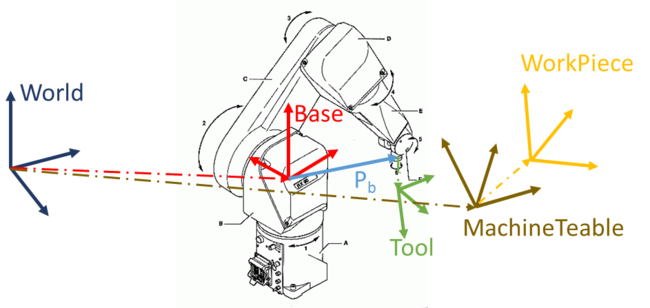
The frames are defined as:
- World - universal frame
- Base - #{X,Y,Z,y,p,r}
- Tool - #{X,Y,Z,y,p,r}
- MachineTable - #{X,Y,Z,y,p,r}
- WorkPiece - #{X,Y,Z,y,p,r}
When # represent Cartesian point coordinate.
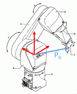
The robot SetPoint parameter defined as the edge point of the robot's tool. When all frames are set to #{0,0,0,0,0,0}, the robot.SetPoint command will show: SetPoint = Pb, when Pb is the vector to the robot edge relative to it's base (NOT the tool edge).
In general, the robot.SetPoint parameter is calculated as follows:
SetPoint = WorkPiece-1:MachineTable-1:Base:Pb:Tool
The relations between the frames and the Pb vector shown here:


Work Space Limits definition
As each frame has it's self limitations, and to define them you should use <Frame>.command, for example:
Base.Xmax = 150
?MachineTable.Zmin
Tool.Zmax = 1230
| NOTE | |
| If these parameters are referred to without a frame, the parameters are set for the WORLD frame |
When a move command is issued, an examination is made to check if the point doesn’t exceed the defined limits.
For Moves and Circle commands, the examination checks that the entire path doesn’t exceed the defined limits. For a Move command, only the final point is examined.
Limits Examination
In order to examine if a certain point is inside the allowed working area, the robot.SetPoint should be transformed into each frame, and then it should be checked that the transformed point is inside the limits of the frame.
The transformations for each frame calculate by the next table:
| Frame | Formula |
|---|---|
| WorkPiece | CheckPoint = SetPoint = WorkPiece-1:MachineTable-1:Base:Pb:Tool
|
| MachineTable | CheckPoint = WorkPiece:SetPoint = MachineTable-1:Base:Pb:Tool
|
| World | CheckPoint = MachineTable:WorkPiece:SetPoint = Base:Pb:Tool
|
| Base | CheckPoint = Base-1:MachineTable:WorkPiece:SetPoint = Pb:Tool
|
| Tool | CheckPoint = Tool-1:Pb,0-1:Base-1:MachineTable:WorkPiece:SetPoint=Tool-1:Pb,0-1:Pb:Tool |
| NOTE | |
| For the Tool frame, the absolute limits are defined relative to Pb at the time that the Tool frame limits were defined. This position is defined as Pb,0 . |
The check protocol start with World frame → Base frame → MachineTable frame → WorkPiece frame → Tool frame,
When each frame coordinates checked from Xmax → Xmin → Ymax → Ymin → Zmax → Zmin
| NOTE | |
| In case that the movement command isn't valid in any parameter, the program will stop checking, and raise an Error Message |
Examples
6 Degree Of Freedom (DOF) Robot
| Frame | Value | Xmin, Xmax | Ymin, Ymax | Zmin, Zmax |
|---|---|---|---|---|
| WorkPiece | #{20,70,150,0,90,-90} | -200, 200 | -200, 200 | -200, 200 |
| MachineTable | #{400,100,0,0,0,0} | 0, 400 | 0, 400 | 0, 800 |
| Base | #{300,200,1000,0,180,180} | -1000, 1000 | -1000, 1000 | 0, 1000 |
| Tool | #{50,0,0,90, 45, 0} | -200, 200 | -200, 200 | -200, 200 |
| World | None | -1500, 1500 | -1500, 1500 | 0, 2000 |
Assume that the desired SetPoint is: #{100,100,0,0,0,0} and that Pb,0 is: #{100,100,900,-45,90,0} - Is it in the work area of the limits?
| Frame | Formula | In Limits? |
|---|---|---|
| WorkPiece | CheckPoint = SetPoint = : #{100,100,0,0,0,0} | Yes
|
| MachineTable | CheckPoint = WorkPiece:SetPoint = #{20,-30,50,0,90,-90} | No - Ymin |
| Base | CheckPoint = Base-1:MachineTable:WorkPiece:SetPoint = #{120,130,950,0,90,90} | Yes
|
| Tool | CheckPoint = Tool-1:Pb,0-1:Base-1:MachineTable:WorkPiece:SetPoint = #{30,100,20,0,0,0} | Yes
|
| World | CheckPoint = MachineTable:WorkPiece:SetPoint = #{420,70,50,0,90,-90} | Yes |
4 Degree Of Freedom (DOF) Robot
| Frame | Value | Xmin, Xmax | Ymin, Ymax | Zmin, Zmax |
|---|---|---|---|---|
| WorkPiece | #{20, 100, 100, 0} | -100, 250 | -300, 30 | -200, 200 |
| MachineTable | #{120, 60, 0, 0} | 0, 700 | 0, 500 | 0, 500 |
| Base | #{0, 0, 0, 0} | -1000, 1000 | -1000, 1000 | 0, 1000 |
| Tool | #{0, 20, 40, 10} | -30, 20 | -30, 20 | -30, 20 |
| World | None | -1500, 1500 | -1500, 1500 | 0, 2000 |
Assume that the desired SetPoint is: #{660, -140, -60, 0} and that Pb,0 is: #{780, -100, -100, 0} - Is it in the work area of the limits?
| Frame | Formula | In Limits? |
|---|---|---|
| WorkPiece | CheckPoint = SetPoint = : #{660, -140, -60, 0} | No- Xmax
|
| MachineTable | CheckPoint = WorkPiece:SetPoint = #{680, -40, 40, 0} | No - Ymin |
| Base | CheckPoint = Base-1:MachineTable:WorkPiece:SetPoint = #{800, 20, 40, 0} | Yes
|
| Tool | CheckPoint = Tool-1:Pb,0-1:Base-1:MachineTable:WorkPiece:SetPoint = #{20, 100, 100, 0} | No - Ymax and Zmax
|
| World | CheckPoint = MachineTable:WorkPiece:SetPoint = #{800, 20, 40, 0} | Yes |
See Also
Links to the commands
