Difference between revisions of "Flying Shear Application"
(→Output) |
|||
| Line 1: | Line 1: | ||
| + | {{Languages|Flying_Shear_Application}} | ||
= Introduction = | = Introduction = | ||
The task of a flying shear application is to cut a constantly moving material to a predefined length. Unlike the punch-cutting, the cutting is done in motion. In flying shear application, the motion task must remain synchronized the master and slave axis for a certain period of time and then go back to the initial position as fast as possible to be ready for the next cut. An optional sensor for length correction can be added. Although this is presented as a cutting application, the example can be used for other applications, such as applying labels or printing markings on the product. The application sets an output when the synchronization point is reached. This output can start the cutting mechanism but could start any other printing or labeling device. | The task of a flying shear application is to cut a constantly moving material to a predefined length. Unlike the punch-cutting, the cutting is done in motion. In flying shear application, the motion task must remain synchronized the master and slave axis for a certain period of time and then go back to the initial position as fast as possible to be ready for the next cut. An optional sensor for length correction can be added. Although this is presented as a cutting application, the example can be used for other applications, such as applying labels or printing markings on the product. The application sets an output when the synchronization point is reached. This output can start the cutting mechanism but could start any other printing or labeling device. | ||
Latest revision as of 02:30, 17 July 2017
| Language: | English • 中文(简体) |
|---|
Introduction
The task of a flying shear application is to cut a constantly moving material to a predefined length. Unlike the punch-cutting, the cutting is done in motion. In flying shear application, the motion task must remain synchronized the master and slave axis for a certain period of time and then go back to the initial position as fast as possible to be ready for the next cut. An optional sensor for length correction can be added. Although this is presented as a cutting application, the example can be used for other applications, such as applying labels or printing markings on the product. The application sets an output when the synchronization point is reached. This output can start the cutting mechanism but could start any other printing or labeling device.
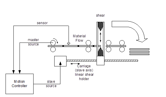
Application Diagram
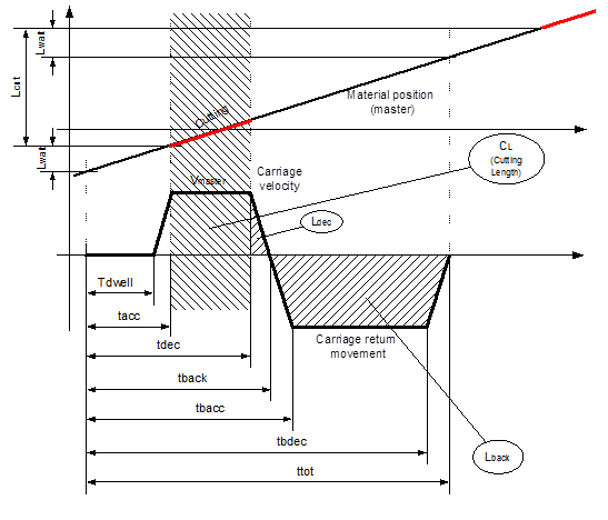
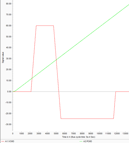
The approximate motion profile for a flying shear application looks like:
Motion profile
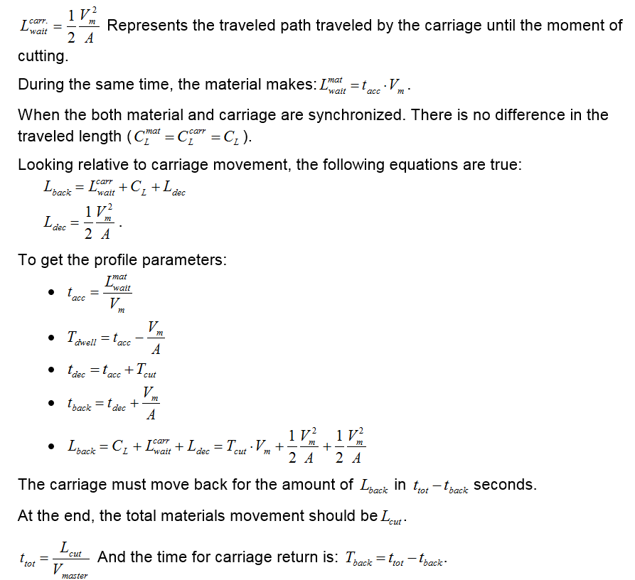
The motion is divided into three phases. The first phase includes the carriage dwell time. The carriage acceleration to the synchronization point is the phase where the carriage should be synchronized to a cut length of the master axis. The second phase or cutting is determined by the time needed for the cutting process to be completed. This phase is determined by cut time or the passed path of the material. The third and last phase is the return of the carriage to its home position. We assume that material flow velocity is constant and known: Vm. Further, we assume that both acceleration and deceleration values are the same. To get the cam profile parameters, use the following equations:
Here, known are L, T and A. The requested are profiler parameters tacc, tdec,v. Using the above equations, the code for the flying shear application is below (using the VTProfile and ProfileLTA routines from the Cut To Length example):
Program
common shared c1 as cam

dim shared toolong   as error "The given cut length is too long for the given slave accel."
dim shared toofast   as error "Slave axis can not move that fast"
dim shared tooshortw as error "Waiting period too short"
' Shared profile parameters:..............................................
dim shared lprof        as double ' total legth
dim shared aprof        as double ' acceleration used
dim shared vprof        as double ' cruise velocity
dim shared t_acc_prof   as double  ' acceleration duration
dim shared t_dec_prof   as double  ' end of cruise phase
dim shared t_tot_prof   as double  ' total velocity trapeze duration
'.........................................................................
program
 dim i  as long

 ' Process data
 dim Vmaster                      as double
 dim CutLength                    as double
 dim CutTime                      as double
 dim DwellTime                    as double
 dim BackLength                   as double
 dim WaitLengthMaster             as double
 dim WaitLengthSlave              as double
 dim DecLength                    as double
 dim CutPath                      as double

 ' Cam profile parameters
 dim t_acc                        as double
 dim t_dec                        as double
 dim t_back                       as double
 dim t_tot                        as double
 dim vback                        as double

 ' Variables used in cam computation
 dim t                            as double
 dim dt                           as double

 WaitLengthMaster  = 15  ' Length in mm that is passed before the carriage is synchronized
 Vmaster           = 60  ' mm/sec - velocity of the material
 CutLength         = 70  ' mm of the master material feed
 CutTime           = 0.2 ' Time 200 ms needed for the cut

 with A1        'A1 = Carriage (Slave)
     Attach
     Slave=0
     FirstCam = none
     CreateCamData 1000 c1               ' Creating 1000 points  in the cam

     CutPath = Vmaster*CutTime           ' Path traveled during cutting process
     t_acc = WaitLengthMaster/Vmaster    ' end of acceleration
     DwellTime = t_acc - Vmaster/acc     ' dwell duration
     if DwellTime < 0 then
        throw tooshortw
     end if

     t_dec  = t_acc + CutTime               ' Time to start deceleration.
     t_back = t_dec + Vmaster/acc           ' Time to starts carriage return
     t_tot  = CutLength/Vmaster             ' Total time of the movement is
     WaitLengthSlave = 0.5*Vmaster^2/acc    ' Path passed by slave during waiting
     DecLength       = 0.5*Vmaster^2/acc    ' Path passed by slave during deceleration
     BackLength      = CutPath + WaitLengthSlave + DecLength ' Total movement length

    ' Setting for the first trapeze (forward carriage motion)
     lprof           = CutPath + WaitLengthSlave + DecLength
     aprof           = acc
     vprof           = Vmaster
     t_acc_prof      = t_acc  - DwellTime
     t_dec_prof      = t_dec  - DwellTime
     t_tot_prof      = t_back - DwellTime

     dt = t_tot/(c1.size-1)
     t = 0
     while t <= t_back
         i = round(t/dt) +1
         c1.MasterData[i] = t*Vmaster
         if t < DwellTime then
              c1.SlaveData[i] = 0
         else
              c1.SlaveData[i]  = VTProfile(t-DwellTime)
         end if
         t = t + dt
     end while


     ' Next trapeze (carriage return)
     lprof           = CutPath + WaitLengthSlave + DecLength
     call ProfileLTA(lprof ,t_tot - t_back, acc)
     while t <= t_tot
         i =     round(t/dt) +1
         c1.MasterData[i] = t*Vmaster
         c1.SlaveData[i]  = BackLength - VTProfile(t-t_back)
         t = t + dt
     end while
     c1.MasterData[c1.size] = CutLength
     c1.SlaveData[c1.size]  = 0


    ' Setup the camming
     c1.Cycle     = -1 ' endless camming
     FirstCam     = c1
     MasterSource = A2.Pcmd
     GearRatio    = 1
     Slave        = cam
     En = ON
     Detach A1
 end with

 Print "Flying Shear Ready"

end program

'.................................................................................
' Velocity Trapeze gernal purpose profile function
' uses shared variables:
' t_acc - time where acceleration ends (cruise starts)
' t_dec - time where deceleration starts (cruise ends)
' t_tot - end of movement
' aprof - accleration/deceleration value
' vprof - cruise (max) velocity
' lprof - total movement length
function VTProfile(byval t as double) as double
  select case(t)
     case is <=0
      VTProfile = 0
     case is <= t_acc_prof
      VTProfile = 0.5*aprof*t^2
     case is <= t_dec_prof
      VTProfile = 0.5*vprof^2/aprof + (t-t_acc_prof)*vprof
     case is < t_tot_prof
      VTProfile = lprof - 0.5*aprof*(t_tot_prof-t)^2
     case else
      VTProfile = lprof
   end select
end function

' Velocity Trapeze pre-calculation routine
' Input: Length, Total time, max Accleration
' Global used: Vmax

sub ProfileLTA(byval L as double ,byval T as double, byval A as double)
    dim sqr as double

    with A1
      aprof = A
      sqr = T^2 - 4*L/A
      select case (sqr)

        case is < -0.004 ' less then 4ms
            throw toolong

        case is < 0
            ' In cases of numeric computation errors (high accel. values) this could be a small
            ' negative number. In order to avoid math error the value is cut to zero.
            sqr = 0

        case else
            sqr = sqrt(sqr)
      end select

      vprof = 0.5*A*(T - sqr)
      if vprof > vmax then
            throw toofast
      end if

      ' Compute fixed points in time (end of acceleration, begin of deceleration)
      t_acc_prof = vprof/A
      t_dec_prof = T - t_acc_prof
      t_tot_prof = T

    end with
end sub


