Difference between revisions of "PLS Timing Issues"
(→Introduction) |
(Delete all HWAssistance description) |
||
| Line 6: | Line 6: | ||
[[ Axystems:MC-Basic:axis.POSITIONERRORDELAY| Axis.PositionErrorDelay]] | [[ Axystems:MC-Basic:axis.POSITIONERRORDELAY| Axis.PositionErrorDelay]] | ||
| − | |||
| − | |||
| − | |||
| − | |||
| − | |||
| − | |||
| − | |||
| − | |||
At samples in motion profile where acceleration profile change its basic formula (jerk discontinuity) there will be an increased error in computing the inter-sample delay (Δt). This is due to the in-availability of exact profile change parameter inside of one sample. Also the higher-order (quadratic, cube, sine, ….) acceleration profiles are not modeled in the inter-sample delay (Δt) calculations, therefore an error of JT3/6 is to be expected. | At samples in motion profile where acceleration profile change its basic formula (jerk discontinuity) there will be an increased error in computing the inter-sample delay (Δt). This is due to the in-availability of exact profile change parameter inside of one sample. Also the higher-order (quadratic, cube, sine, ….) acceleration profiles are not modeled in the inter-sample delay (Δt) calculations, therefore an error of JT3/6 is to be expected. | ||
Revision as of 14:24, 14 May 2014
Contents
Introduction
This document describes timing issues of PLS triggering.
The following variables influence PLS timing.
At samples in motion profile where acceleration profile change its basic formula (jerk discontinuity) there will be an increased error in computing the inter-sample delay (Δt). This is due to the in-availability of exact profile change parameter inside of one sample. Also the higher-order (quadratic, cube, sine, ….) acceleration profiles are not modeled in the inter-sample delay (Δt) calculations, therefore an error of JT3/6 is to be expected.
In all cases of non-linear acceleration change:
- sine acceleration
- one-sample duration movements
- velocity-trapeze corners
- acceleration-trapeze corners
- extreme acceleration (so acc phase duration is 1 sample) or very short movement
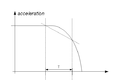
Illustration 1: Error introduced due to the jerk value in sine-acceleration profile at the transition sample between acceleration saturation and acceleration decrease
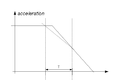
Illustration 2: Error introduced due to the acceleration change in trapeze-acceleration profile at the transition sample between acceleration saturation and acceleration decrease
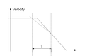
Illustration 3: Error introduced due to the transition point between cruise velocity and deceleration in trapeze-velocity profile


there will be an increased error in computing of the inter-sample delay (Δt)! It is very difficult to estimate the position error introduced but it is typically around JT3/6.
| NOTE | |
| Note that in cases of extremely short motions (velocity or acceleration too high or path length too short) even if user commanded sine-acceleration profile the system will automatically change it to velocity-trapeze. |
| NOTE | |
| Note that currently in fw 4.5.29 and older there is not distinction between different PLS sources. If PLS is triggered by a “feedback” source like PFB or PEXT we will always have PLS triggered too late. But in this case no additional delay should be added! |
Buffering
As noted in previous paragraphs the delay of the motion-bus forces the system to postpone the switching of the PLS output. Therefore the detected PLS output switch events are stored in the buffer and executed after the estimated delay.
There are two different buffers (per each PLS) dedicated for the PLS delayed outputs:
- Motion-Bus PLS delay Buffer, used for storing PLS-delays through multiple sampling periods. The size of this buffer is: 2 (FW ver: 4.5.29) - 4*10(FW ver: 4.5.31 and later)
- Digital Output microsecond delay buffer. Used for storing microsecond delays of only one motion-bus sample. The size of this buffer is 4 and it is hardware defined.
| NOTE | |
| Note that in the systems with relatively big motion-bus delay (PositionErrorDelay >> 3) number of the stored PLS switches can be bigger then the Motion-Bus Delay Buffer size. In this case the error returned will be 3298: "The PLS positions are too close to each other and/or the velocity is too high for output to toggle". In case there is more then 4 PLS in one sample the IO error will be returned 21011: "Too many PLS toggling requested ". |
PLSPropagationDelay
See: PLSPropagationDelay
Debug variables (new properties)
Two read-only properties returning in microseconds the time of the IO toggle. If not initiated -1 will be returned.
<pls>.HWIOtime[<index>]
See: HWIOtime
<pls>.PLSdelaytime[<index>]
See: PLSdelaytime
General illustration of PLS-timing

--Mirko 10:23, 15 November 2010 (CET)