Difference between revisions of "softMI HMI Getting started"
| (13 intermediate revisions by the same user not shown) | |||
| Line 1: | Line 1: | ||
| − | |||
| − | |||
| − | + | This is a tutorial for first configuration of SoftMC with SoftMI through HMIStudio. | |
| + | |||
| + | | ||
| + | |||
| + | == Access HMI properties and IP configuration == | ||
| + | |||
| + | Turn HMI power off. Long press anywhere on the screen. Turn HMI power on. | ||
| + | |||
| + | Now properties windows pops up at power on. Notice, changing IP address will only saved after downloading initial project to HMI. | ||
| + | |||
== Creating project and adding network components == | == Creating project and adding network components == | ||
| − | Open new project:<br /> | + | Open new project:<br/> [[File:HMI18.png|RTENOTITLE]] |
| − | [[File:HMI18.png]] | ||
At the left side bar - "Graph Element Window" select HMI tab, and choose HMI type. | At the left side bar - "Graph Element Window" select HMI tab, and choose HMI type. | ||
| + | [[File:HMI2.png|RTENOTITLE]] | ||
| − | + | At the left side bar - "Graph Element Window" select PLC tab, and choose controller / PLC type.<br/> Drag and drop in center window: | |
| − | + | [[File:HMI3.png|RTENOTITLE]] | |
| − | |||
| − | + | At the left side bar - "Graph Element Window" select Connector tab, and choose communication type.<br/> In this example I choose Ethernet (TCP)<br/> Drag and drop in center window: | |
| − | + | [[File:HMI4.png|RTENOTITLE]] | |
| − | |||
| − | |||
| − | + | At the pop up window - "Network Device Setting" press "Add".<br/> Set HMI IP, and choose correct Comm Protocol: | |
| − | + | [[File:HMI5.png|RTENOTITLE]] | |
| − | |||
| − | + | Press "Add" again, and set SoftMC IP and comm protocol: | |
| − | + | [[File:HMI6new.png|RTENOTITLE]] | |
| − | + | After adding both HMI and PLC this is the final display: | |
| − | + | [[File:HMI7new.png|RTENOTITLE]] | |
| − | + | Double click the HMI for access extra Attribute configure: | |
| − | + | [[File:HMI8.png|RTENOTITLE]] | |
| − | + | | |
| + | |||
| + | | ||
== Importing Parameters file (CSV) == | == Importing Parameters file (CSV) == | ||
| − | SoftMC Modbus Configurator is generating CSV file containing the project parameters and their Modbus addresses. | + | SoftMC Modbus Configurator is generating CSV file containing the project parameters and their Modbus addresses. |
| − | Generating CSV file with Modbus Configurator [[http://softmc.servotronix.com/wiki/Modbus_Communication_API#Modbus_Configurator]] | + | Generating CSV file with Modbus Configurator [[http://softmc.servotronix.com/wiki/Modbus_Communication_API#Modbus_Configurator [1]]] |
| − | Importing the CSV file to HMIStudio:<br /> | + | Importing the CSV file to HMIStudio:<br/> Go to “Project Database” tab in “Graph Element Window”, and choose “Address Tag”: |
| − | Go to “Project Database” tab in “Graph Element Window”, and choose “Address Tag”: | ||
| − | [[File:HMI9.png]] | + | [[File:HMI9.png|RTENOTITLE]] |
| − | Import the CSV File: | + | Import the CSV File: |
| − | [[File:HMI10.png]] | + | [[File:HMI10.png|RTENOTITLE]] |
| + | |||
| + | Once the .CSV file was selected, the parameters (Modbus Tags) should appear in the Address Tag list. | ||
| + | |||
| + | [[File:Picture1.png|RTENOTITLE]] | ||
| + | |||
| + | '''Note''': If the Modbus Tags do not appear on the list, make sure the "AddrPLCID" in the .CSV file is similar to the defined PLC Controller. If not, change the address in the .CSV, save it and import the file again | ||
| + | |||
| + | [[File:csvadr.JPG|1000x500px|csvadr.JPG]] | ||
| + | |||
| + | | ||
| − | |||
== Build and design the interface == | == Build and design the interface == | ||
| − | |||
| − | |||
| − | + | Operations in HMI screen are carried out through Components.<br/> In this components user can execute SoftMC Functionality, read and write data. | |
| − | + | To enter screen design window, Right click on HMI, and “'''Edit'''”: | |
| − | + | [[File:HMI12.png|RTENOTITLE]] | |
| − | + | Basic components are located at "Graph Element Window" at "'''PLC Parts'''": | |
| − | + | Lets create an ON / OFF button, which will use the Modbus tag “ENAB” and “DISAB”. | |
| − | |||
| − | [[File: | + | [[File:HMI13.png|RTENOTITLE]] |
| − | + | Drag and drop required component to center window (HMI Screen).<br/> When doing so, arttribute of the component will open: | |
| − | + | ||
| + | 1.Select “'''Bit State Switch'''”. | ||
| + | |||
| + | 2.Select “'''Use Address Tag''':”. | ||
| + | |||
| + | 3.In Addr. Type, select the desired parameter. | ||
| + | |||
| + | 4.Select “'''Bit State Switch'''”. | ||
| + | |||
| + | 5.In Switch Type, select “'''Reset'''”. This will reset the button and return it to “0” value. | ||
| + | |||
| + | [[File:onoffbutton.JPG|1000x500px|onoffbutton.JPG]] | ||
| + | |||
| + | <span style="font-size:larger;">'''Repeat the procedure for “DISAB” Modbus tag.'''</span> | ||
| + | |||
| + | | ||
| + | |||
| + | Now lets add a bit lamp, which will indicate whether the drive is ON or OFF. | ||
| + | |||
| + | 1.Select “Bit State Switch”. Remember ENAB Register Type is a “Bit” | ||
| + | |||
| + | 2.Select “Use Address Tag:”. | ||
| + | |||
| + | 3.In Addr. Type, select the desired parameter. | ||
| + | |||
| + | [[File:bitlamp.JPG|1000x500px|bitlamp.JPG]] | ||
| + | |||
| + | The final screen should look lie this: | ||
| + | |||
| + | [[File:Picture3.png|700x400px|Picture3.png]] [[File:Picture2.png|700x400px|Picture2.png]] | ||
== Component Attribute == | == Component Attribute == | ||
| − | |||
| − | |||
| − | [[File:HMI15.png]] | + | It is important to fully configure the component, in means of data tpye, size, operation, etc.<br/> For example, when adding number display, which is a 16bit register (Hreg), make sure “Data width” is according to what configured in softMC Modbus configurator: |
| + | |||
| + | [[File:HMI15.png|RTENOTITLE]] | ||
| + | |||
| + | *“Word” is 16bit | ||
| + | |||
| + | In SoftMC: | ||
| + | |||
| + | *“Short” = 16bit | ||
| + | *“Long” = 32bit | ||
| − | |||
| − | |||
| − | |||
| − | |||
So if chosen parameter as “long”, choose DWORD (double word). | So if chosen parameter as “long”, choose DWORD (double word). | ||
| + | |||
| + | |||
== Download project to HMI == | == Download project to HMI == | ||
| − | |||
| − | |||
| − | [[File:HMI16.png]] | + | First project download ('''brand new HMI from the box''') must be performed through serial communication. Wiring: |
| + | |||
| + | [[File:HMI16.png|RTENOTITLE]] | ||
| + | |||
| + | '''Note''': If the computer does not support RS232 input, an RS232 to USB '''adapter '''can be used. | ||
| + | |||
| + | [[File:wiring.jpeg|700x500px|wiring.jpeg]] | ||
| + | |||
| + | Once connected with serial connection, in the tool bar, select “Tools” > “Compile All(R)”. | ||
| + | |||
| + | Then “Tools” > “Download Way(A)”> Download Device select: “Com”. | ||
| + | |||
| + | [[File:HMI17.png|RTENOTITLE]] | ||
| + | |||
| + | [[File:commportjpg.jpg|RTENOTITLE]] | ||
| + | |||
| + | '''Note''': There are 9 COM numbers available in “PC Serial No.”. However, the device may have received a different COM number, which is higher then 9. That is OK, select any COM from COM1-COM9. | ||
| + | |||
| + | If the device received a COM number, which is higher then 9, it should be modified to match the selected COM number chosen in the previous slide (See Below). If the device received a COM number, which is lower then 9, change the COM in the “PC Serial No.” to match the device COM. | ||
| + | |||
| + | •Right click on the Computer > Manage > Device Manager. | ||
| + | |||
| + | •Locate you device and check COM number. If it is Higher then 9, go through steps 1-5. | ||
| + | |||
| + | '''Note''': COM1-9 may be already in use. Select the desired COM number and continue anyway. | ||
| + | |||
| + | [[File:commportjpg2.jpg|1200x450px|commportjpg2.jpg]] | ||
| + | |||
| + | Now go back to HMIStudio, select the correct COM number and click OK. | ||
| − | [[File: | + | [[File:commportjpg.jpg|RTENOTITLE]] |
| − | + | To download the project to the HMI, go to “'''Tools'''” > “'''Download(D)'''" and click Download. | |
| − | + | ||
| − | + | [[File:Picture4.png|RTENOTITLE]] | |
| − | |||
| − | + | [[Category:Modbus Communication]] | |
| − | |||
Latest revision as of 11:57, 10 February 2020
This is a tutorial for first configuration of SoftMC with SoftMI through HMIStudio.
Contents
Access HMI properties and IP configuration
Turn HMI power off. Long press anywhere on the screen. Turn HMI power on.
Now properties windows pops up at power on. Notice, changing IP address will only saved after downloading initial project to HMI.
Creating project and adding network components
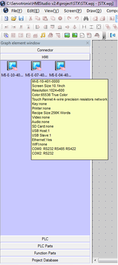
At the left side bar - "Graph Element Window" select HMI tab, and choose HMI type.
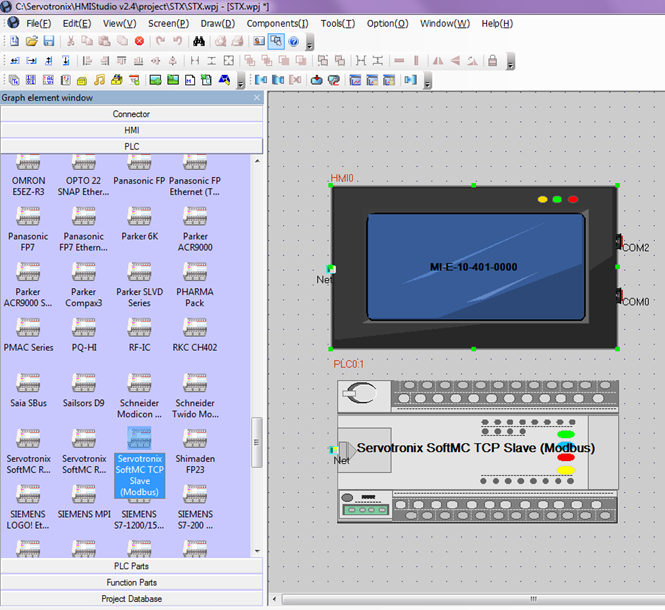
At the left side bar - "Graph Element Window" select PLC tab, and choose controller / PLC type.
Drag and drop in center window:
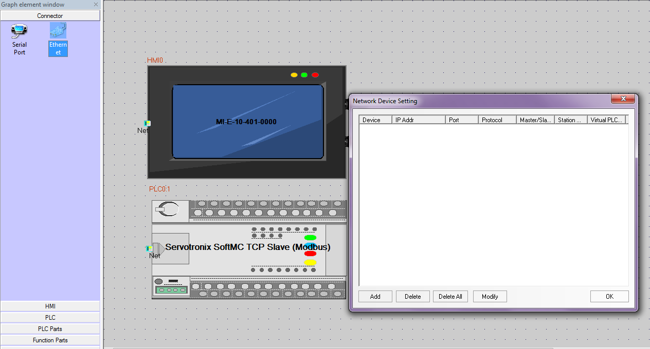
At the left side bar - "Graph Element Window" select Connector tab, and choose communication type.
In this example I choose Ethernet (TCP)
Drag and drop in center window:
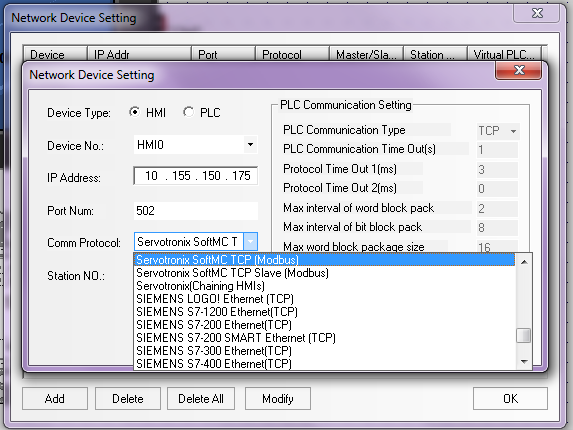
At the pop up window - "Network Device Setting" press "Add".
Set HMI IP, and choose correct Comm Protocol:
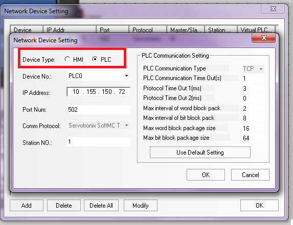
Press "Add" again, and set SoftMC IP and comm protocol:
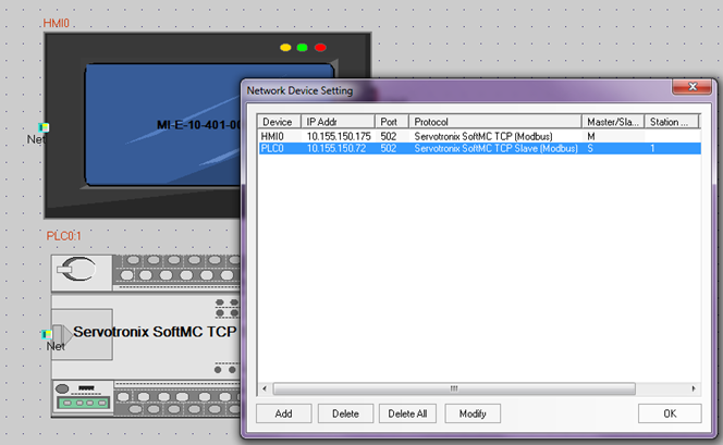
After adding both HMI and PLC this is the final display:
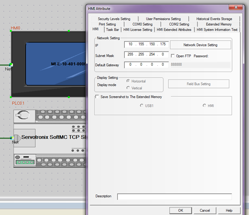
Double click the HMI for access extra Attribute configure:
Importing Parameters file (CSV)
SoftMC Modbus Configurator is generating CSV file containing the project parameters and their Modbus addresses.
Generating CSV file with Modbus Configurator [[1]]
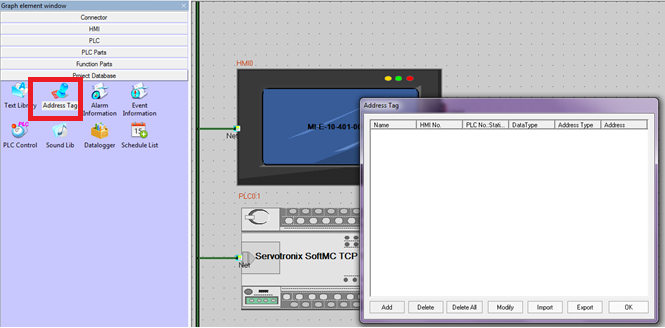
Importing the CSV file to HMIStudio:
Go to “Project Database” tab in “Graph Element Window”, and choose “Address Tag”:
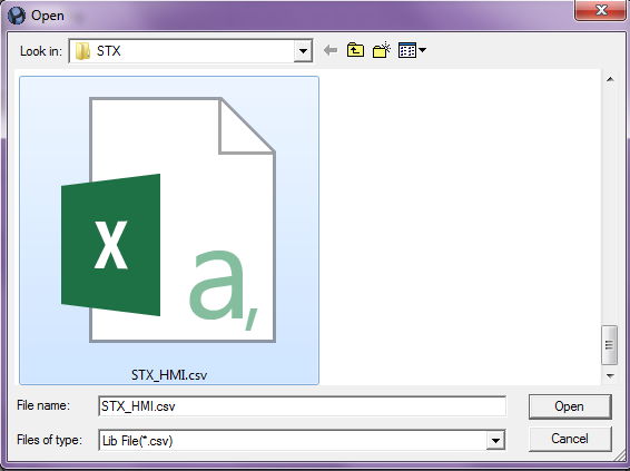
Import the CSV File:
Once the .CSV file was selected, the parameters (Modbus Tags) should appear in the Address Tag list.
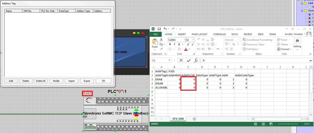
Note: If the Modbus Tags do not appear on the list, make sure the "AddrPLCID" in the .CSV file is similar to the defined PLC Controller. If not, change the address in the .CSV, save it and import the file again
Build and design the interface
Operations in HMI screen are carried out through Components.
In this components user can execute SoftMC Functionality, read and write data.
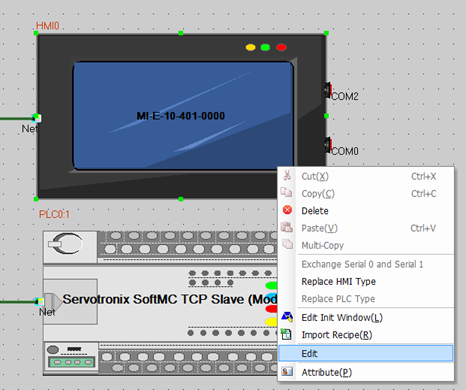
To enter screen design window, Right click on HMI, and “Edit”:
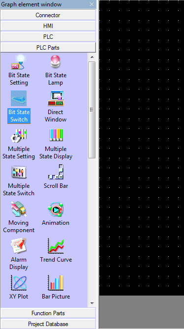
Basic components are located at "Graph Element Window" at "PLC Parts":
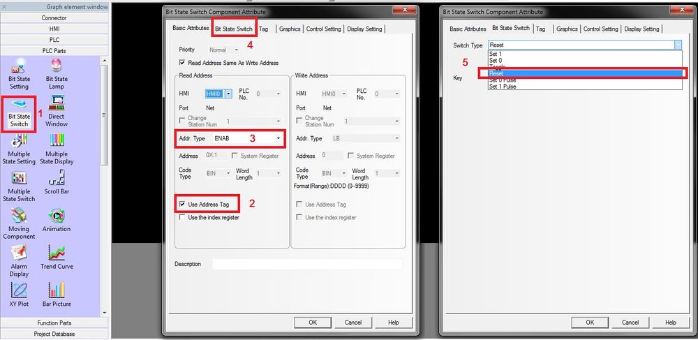
Lets create an ON / OFF button, which will use the Modbus tag “ENAB” and “DISAB”.
Drag and drop required component to center window (HMI Screen).
When doing so, arttribute of the component will open:
1.Select “Bit State Switch”.
2.Select “Use Address Tag:”.
3.In Addr. Type, select the desired parameter.
4.Select “Bit State Switch”.
5.In Switch Type, select “Reset”. This will reset the button and return it to “0” value.
Repeat the procedure for “DISAB” Modbus tag.
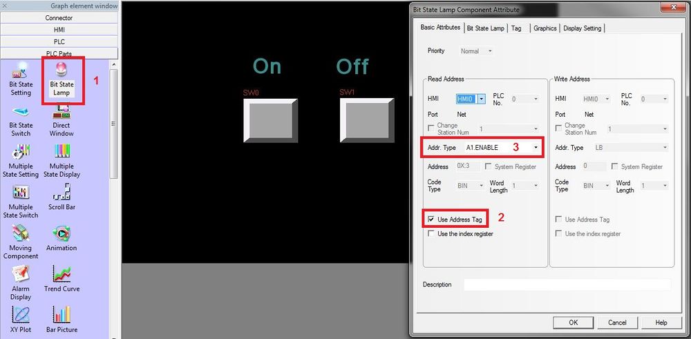
Now lets add a bit lamp, which will indicate whether the drive is ON or OFF.
1.Select “Bit State Switch”. Remember ENAB Register Type is a “Bit”
2.Select “Use Address Tag:”.
3.In Addr. Type, select the desired parameter.
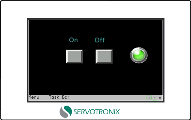
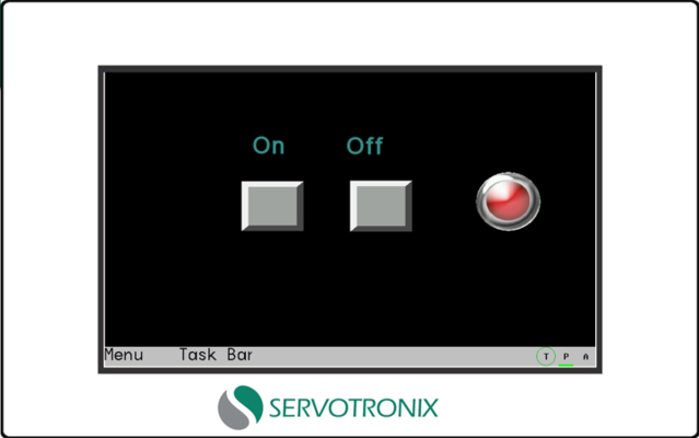
The final screen should look lie this:
Component Attribute
It is important to fully configure the component, in means of data tpye, size, operation, etc.
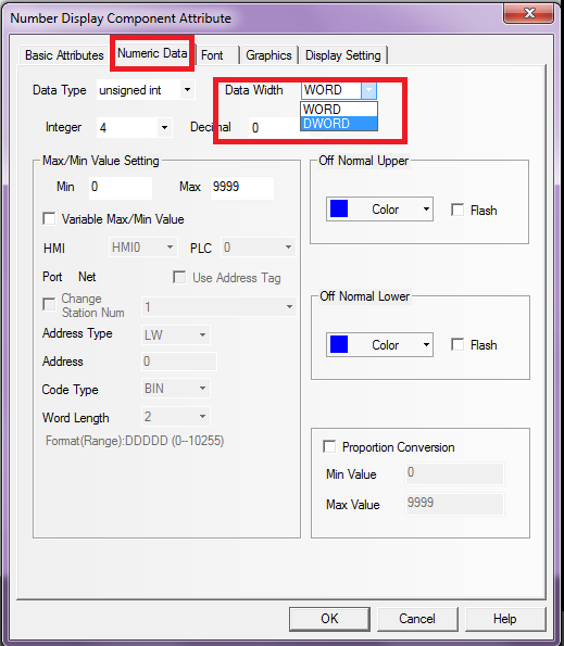
For example, when adding number display, which is a 16bit register (Hreg), make sure “Data width” is according to what configured in softMC Modbus configurator:
- “Word” is 16bit
In SoftMC:
- “Short” = 16bit
- “Long” = 32bit
So if chosen parameter as “long”, choose DWORD (double word).
Download project to HMI
First project download (brand new HMI from the box) must be performed through serial communication. Wiring:
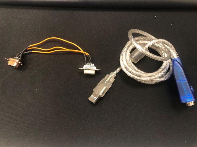
Note: If the computer does not support RS232 input, an RS232 to USB adapter can be used.
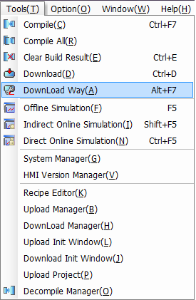
Once connected with serial connection, in the tool bar, select “Tools” > “Compile All(R)”.
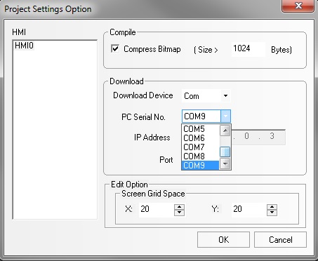
Then “Tools” > “Download Way(A)”> Download Device select: “Com”.
Note: There are 9 COM numbers available in “PC Serial No.”. However, the device may have received a different COM number, which is higher then 9. That is OK, select any COM from COM1-COM9.
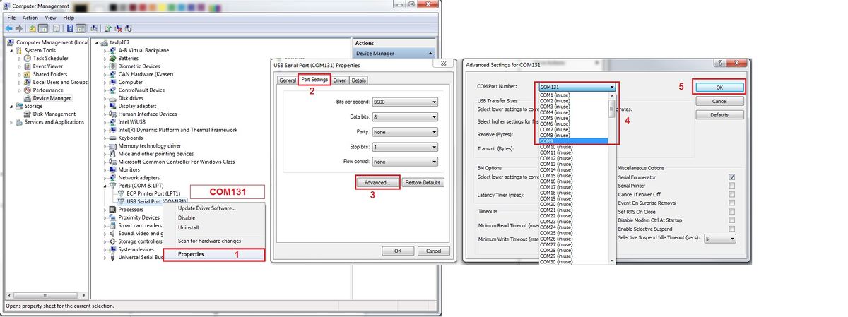
If the device received a COM number, which is higher then 9, it should be modified to match the selected COM number chosen in the previous slide (See Below). If the device received a COM number, which is lower then 9, change the COM in the “PC Serial No.” to match the device COM.
•Right click on the Computer > Manage > Device Manager.
•Locate you device and check COM number. If it is Higher then 9, go through steps 1-5.
Note: COM1-9 may be already in use. Select the desired COM number and continue anyway.
Now go back to HMIStudio, select the correct COM number and click OK.
To download the project to the HMI, go to “Tools” > “Download(D)" and click Download.

