Difference between revisions of "Cut To Length (Punching) Application"
| (One intermediate revision by the same user not shown) | |||
| Line 1: | Line 1: | ||
| − | {{Languages}} | + | {{Languages|Cut_To_Length_(Punching)_Application}} |
| − | = | + | = Introduction = |
| − | + | An eccentric press (crank press) is being feed by a servo-driven feeding device cammed to the angular position of the wheel. The wheel position is measured by an external feedback device (resolver, encoder, etc.) that is connected to a drive as an external position signal (PEXT). | |
| − | = | + | = Application Diagram = |
[[File:cut2len1.png]] | [[File:cut2len1.png]] | ||
| − | + | The angular position of the wheel is the master source signal that continuously increases during its operation. On each turn of the wheel, there is a start and end angle value where the feed axis should stop. | |
| − | = | + | = Motion profile = |
| − | + | The feed axis operation looks like: | |
[[File:cut2len2.png]] | [[File:cut2len2.png]] | ||
| − | + | The main task in building this application is to design a cam according to the following parameters: | |
| − | • | + | • Total wheel turn angle, value of pext needed for one full turn of the wheel. |
| − | • | + | • Start angle, wheel angle where the punching starts |
| − | • | + | • End angle, wheel angle where the material can be moved or when the punching ends. |
| − | • | + | • Length of the cut, the distance of slave position between the last end-angle to the next start-angle of the wheel. |
| − | • | + | • Maximum acceleration and velocity of the slave axis, these values can not be exceeded during camming. |
| − | + | An additional limitation is the decision to take velocity trapezoidal profile for the slave motion. Another profile could be taken, but the equations would differ. | |
| − | + | The wheel velocity is assumed to be constant and known for the computations. Now, to compute a motion profile from the given A, L, T values, see Appendix at end of example. | |
| − | = | + | = Program = |
<syntaxhighlight lang="vb"> | <syntaxhighlight lang="vb"> | ||
common shared c1 as cam | common shared c1 as cam | ||
| Line 171: | Line 171: | ||
''' | ''' | ||
| − | = | + | = Profile recording = |
| − | + | Two turns of the master wheel (cut length 20 mm): | |
[[File:cut2len4.PNG]] | [[File:cut2len4.PNG]] | ||
| − | + | A 35 mm length close to triangular profile: | |
[[File:cut2len5.png]] | [[File:cut2len5.png]] | ||
| − | = | + | = Computing velocity profile with known A, L, T = |
[[File:cut2len3.PNG]] | [[File:cut2len3.PNG]] | ||
Latest revision as of 15:36, 27 November 2017
| Language: | English • 中文(简体) |
|---|
Contents
Introduction
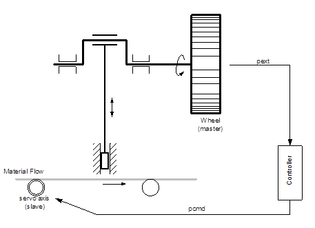
An eccentric press (crank press) is being feed by a servo-driven feeding device cammed to the angular position of the wheel. The wheel position is measured by an external feedback device (resolver, encoder, etc.) that is connected to a drive as an external position signal (PEXT).
Application Diagram
The angular position of the wheel is the master source signal that continuously increases during its operation. On each turn of the wheel, there is a start and end angle value where the feed axis should stop.
Motion profile
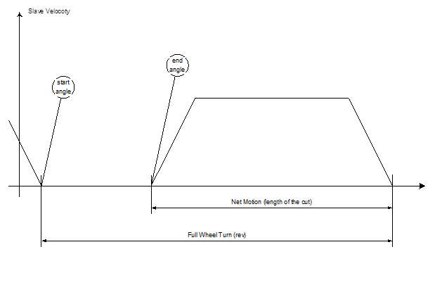
The feed axis operation looks like:
The main task in building this application is to design a cam according to the following parameters: • Total wheel turn angle, value of pext needed for one full turn of the wheel. • Start angle, wheel angle where the punching starts • End angle, wheel angle where the material can be moved or when the punching ends. • Length of the cut, the distance of slave position between the last end-angle to the next start-angle of the wheel. • Maximum acceleration and velocity of the slave axis, these values can not be exceeded during camming. An additional limitation is the decision to take velocity trapezoidal profile for the slave motion. Another profile could be taken, but the equations would differ. The wheel velocity is assumed to be constant and known for the computations. Now, to compute a motion profile from the given A, L, T values, see Appendix at end of example.
Program
common shared c1 as cam

dim shared toolong as error "The given cut length is too long for the given slave accel."
dim shared toofast as error "Slave axis can not move that fast"

' Shared profile parameters:..............................................
dim shared lprof        as double  ' total length
dim shared aprof        as double  ' acceleration used
dim shared vprof        as double  ' cruise velocity
dim shared t_acc_prof   as double  ' acceleration duration
dim shared t_dec_prof   as double  ' end of cruise phase
dim shared t_tot_prof   as double  ' total velocity trapeze duration
'.........................................................................

program
    ' Process data
    dim sangle      as double = 10  ' start to cut at this angle
    dim eangle      as double = 60  ' finish the cut at this angle
    dim rev         as double = 360 ' full turn of the wheel
    dim Vwheel      as double = 60  ' RPM - velocity of the wheel

    dim CutLength   as double = 20  ' mm of the slave motion
    dim CutAngle    as double
    dim CutTime     as double
    dim i           as long

    ' Variables used in cam computation
    dim t           as double
    dim t_from_end  as double

    ' Creating 1000 points in the cam
     createcamdata 1000 c1

    ' Computing the next motion
    CutAngle = rev - (eangle-sangle)    ' The wheel passes this angel while it moves
    CutTime  = CutAngle/(Vwheel*360/60) ' Time needed to move to another cut (sec)
    with A1

        call ProfileLTA(CutLength,CutTime,Acc)

        ' Start computing the cam table
        ' t is relative time of velocity trapeze profile
        for i = 1 to c1.size
           c1.MasterData[i] = (i-1)*rev/c1.size ' Defining a uniform master axis

           select case (c1.MasterData[i])
              case is < sangle     ' it is a rotary axis in cases when master < start
                  ' we need to compute the relative time from the end
                  t_from_end = (sangle - c1.MasterData[i])/(Vwheel*360/60)
                  t = CutTime - t_from_end
                  c1.SlaveData[i] = VTProfile(t)  - CutLength

              case is <= eangle    ' master is between start and end - no motion of slave:
                  c1.SlaveData[i] = 0.0

              case is > eangle     ' Time passed after exit [start,end] master segment
                  t = (c1.MasterData[i]-eangle)/(Vwheel*360/60)
                  c1.SlaveData[i] = VTProfile(t)

           end select
        next
    end with

    with A2
        ' Setup the cam table
        c1.Cycle            = -1 ' endless camming
        Attach
           FirstCam         = c1
           MasterSource     = A1.Pcmd   'For example with 2 axes
'           MasterSource    = pext
           GearRatio        = 1
           Slave            = CAM
           SlaveDisconnect  = 0
           En               = ON
        Detach

    end with

    Print "Cut to length Ready"

end program


' Velocity Trapeze pre-calculation routine
' Input: Length, Total time, max Accleration
' Global used: Vmax

sub ProfileLTA(byval L as double ,byval T as double, byval A as double)
    dim sqr as double

    with A1
      aprof = A
      sqr = T^2 - 4*L/A
      select case (sqr)

        case is < -0.004 ' less then 4ms
            throw toolong

        case is < 0
            ' In cases of numeric computation errors (high accel. values) this could be a small
            ' negative number. In order to avoid math error the value is cut to zero.
            sqr = 0

        case else
            sqr = sqrt(sqr)
      end select

      vprof = 0.5*A*(T - sqr)
      if vprof > vmax then
            throw toofast
      end if

      ' Compute fixed points in time (end of acceleration, begin of deceleration)
      t_acc_prof = vprof/A
      t_dec_prof = T - t_acc_prof
      t_tot_prof = T

    end with
end sub


'.................................................................................
' Velocity Trapeze gernal purpose profile function
' uses shared variables:
' t_acc - time where acceleration ends (cruise starts)
' t_dec - time where deceleration starts (cruise ends)
' t_tot - end of movement
' aprof - accleration/deceleration value
' vprof - cruise (max) velocity
' lprof - total movement length
function VTProfile(byval t as double) as double
  select case(t)
     case is <=0
      VTProfile = 0
     case is <= t_acc_prof
      VTProfile = 0.5*aprof*t^2
     case is <= t_dec_prof
      VTProfile = 0.5*vprof^2/aprof + (t-t_acc_prof)*vprof
     case is < t_tot_prof
      VTProfile = lprof - 0.5*aprof*(t_tot_prof-t)^2
     case else
      VTProfile = lprof
   end select
end function
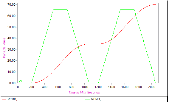
Profile recording
Two turns of the master wheel (cut length 20 mm):
A 35 mm length close to triangular profile:


