|
|
| (5 intermediate revisions by the same user not shown) |
| Line 1: |
Line 1: |
| − | {{Languages}} | + | {{Languages|Element_Coordination}} |
| − | = 介绍 = | + | =全局坐标概念 = |
| | | | |
| − | 此功能的主要目标是几个机器人的空间和时间上运动同步。这将使用系统中存在的标准主 - 从关系将其扩展为通用机器人到机器人连接。将要使用的功能是'''移动坐标系特性''',通常用于'''传输带跟踪'''。移动坐标系的源将从简单的轴列表扩展到任何机器人类型的笛卡尔命令(SETPOINT,HERE)。
| + | 对于使用不同点类型的''全局坐标概念''的机器人已经被定义。 这允许以一种常见的独特格式给予机器人位置,以独立地观察机器人具有多少轴。 这里使用的关键属性是机器人的[[MC-Basic:robot.BASE|base]]变换,如[[Robot Working Frames|Robot_Working_Frames]]所述 |
| | | | |
| − | 主机器人是从机器人跟随的移动坐标系的主源。 将使用相同的同步算法,除了与跟踪窗口和触发相关的问题(这两个将是无关紧要的)。
| + | == 基坐标系属性 == |
| | + | 机器人有两个笛卡尔坐标系:世界(机器人)坐标系和基坐标系。 |
| | | | |
| − | 跟踪期间从机器人的相对运动是允许的,在常规的输送机跟踪以相同的方式执行。
| + | === 世界(机器人)坐标系 === |
| | | | |
| − | 机器人的相互空间关系将通过新添加的基坐标系和移动坐标系的对象位置偏移来定义。 与此同时,可以实现不同点类型(世界(机器人)框架)和/或不同NDOF的机器人的相互协作。
| + | 在由''q = (q<sub>1</sub>,q<sub>2</sub>,q<sub>3</sub>, .... , q<sub>n</sub>)''定义的机器人姿势中,n是机器人的NDOF。 世界(机器人)参考坐标由下式定义: |
| | | | |
| | + | <center>'''''p<sub>world</sub> = DirectKinematics (q)'''''</center> |
| | | | |
| | + | 其中p可以是:p =(x,y,z,偏航,俯仰,滚动)取决于机器人运动学。 |
| | | | |
| − | {{Note/Important| 只有在机器人具有相同点类型的情况下,才能使用完整的位置(位置+姿态)。 在具有不同点类型的机器人的情况下,仅跟踪主机器人位置的位置部分(X,Y,Z)。 姿态角(Yaw,Pitch,Roll)将 '''被忽略 '''}} | + | {{Note|为了简化讨论,我们假定该'''''工具'''''包含在正运动学计算中。这里省略了工件和工作台的坐标系。}} |
| | | | |
| | | | |
| − | {{Note/Important| 在具有相同点类型的机器人的情况下,用户能够选择是仅仅在位置或姿态坐标上进行跟踪或者在两者上进行跟踪。请参阅[[MC-Basic:movingFrame.TYPE|MovingFrame.type]]属性。}}
| + | === 基坐标系 === |
| | | | |
| | + | 基坐标系是由[[MC-Basic:robot.BASE|robot.base]]属性移动的世界(机器人)坐标系: |
| | | | |
| − | {{Note| 在跟踪期间检测(监控)轴的位置限制和加速度/速度阈值,方式与常规传送带跟踪相同。 }}
| + | p<sub>base</sub> = base:p<sub>world</sub> |
| | | | |
| | + | 其中''':'''是复合运算符。 |
| | | | |
| − | {{Note/Danger|需要重要强调的是此功能(使用基于机器人的运动坐标系的元素协作)'''不会'''阻止机器人碰撞。 机器人防碰撞完全脱离了这个主题。}}
| + | == 全局基坐标属性(全局坐标) == |
| | | | |
| − | = 系统设置 =
| + | 所有用户输入(目标运动指令点,运动参考坐标等)都在基座坐标系中给出。 然而,这些系统可以与机器人不同(例如,R1具有XYZR和R2具有XYZYPR)。 因此,我们假设一个共同的(全局)基坐标系,将所有机器人转换到一个系统: |
| | | | |
| − | == 数据创建 == | + | p<sup>1</sup><sub>global</sub> = '''R1.glbalbase''':R1.base:R1.DirectKinemaitcs(R1.pcmd) <br> |
| | + | p<sup>2</sup><sub>global</sub> = '''R2.glbalbase''':R2.base:R2.DirectKinemaitcs(R2.pcmd) <br> |
| | + | p<sup>3</sup><sub>global</sub> = '''R3.glbalbase''':R3.base:R3.DirectKinemaitcs(R3.pcmd) <br> |
| | + | ...<br> |
| | + | p<sup>m</sup><sub>global</sub> = '''Rm.glbalbase''':Rm.base:Rm.DirectKinemaitcs(Rm.pcmd) <br> |
| | | | |
| − | ControlStudio中有两种运动参考系(MF)对象:基于轴和基于机器人。它们都以与使用该命令的基于轴的方式以相同的方式创建:<br>
| + | 假设系统有''m''个机器人 |
| | | | |
| − | <center>'''COMMON SHARED <mf name> as moving frame of <mf-type>'''</center><br>
| + | 这是通过添加始终与实际机器人点类型无关的[[MC-Basic:robot.GLOBALBASE|<robot>.globalbase]]位置来实现的,在XYZYPR系统中给出 |
| | | | |
| − | 基于轴和基于机器人的运动参考系之间的差异在提供给 '''[[MC-Basic:movingFrame.MASTERSOURCE| MasterSource]]''' 命令的参数中。在<u>基于轴<u>的MF中,仅使用主轴作为主源。此外,在<u>基于轴<u>的MF中,所有位置MF的属性(零,此处,上行,下行)的点类型与MF的点类型(即<mf-type>)相同。<br>
| |
| | | | |
| − | 在<u>基于机器人</u> 的MF的主源是具有自己的点类型的机器人元素。在<u>基于机器人<u>的MF中,MF的位置和机器人的位置之间的关系将使用新引入的属性来定义。 ''(参考: Translation Transformation )''
| + | <div style="background-color:yellow;"> |
| | + | '''为了使全局坐标系尽可能的使用,运动命令(MOVE,MOVES,MOVESKD,CIRCLE ...)的扩展方式除了目前仅允许的机器人点类型的位置之外,还可以接受XYZYPR点类型的位置。 |
| | + | ''' |
| | + | </div> |
| | | | |
| − | == 主源 ==
| |
| | | | |
| − | [[MC-Basic:movingFrame.MASTERSOURCE|<Moving Frame>.MasterSource]]属性将允许将机器人元素的命令(setpoint)或反馈(here)添加为主站,以下句法将有效:
| + | {{Note|给定的扩展适用于最多6个NDOF(不超过6个)的机器人。}} |
| | | | |
| − | [[MC-Basic:movingFrame.MASTERSOURCE|<Moving Frame>.MasterSource]] = <robot>.setpoint
| |
| − | and
| |
| − | [[MC-Basic:movingFrame.MASTERSOURCE|<Moving Frame>.MasterSource]] = <robot>.here
| |
| | | | |
| − | {{Note|'''master'''<robot>的点类型不必与<nowiki><moving frame></nowiki>的点类型匹配! | + | {{Note| 如果机器人点类型已经是XYZYPR,则全局和基本属性具有绝对相同的功能,可以相互添加。 他们都可以使用,但我们强烈建议只使用一个(而另一个保留为零),以减少混乱。}} |
| − | 但是,<nowiki><moving frame></nowiki>和'''从'''机器人的类型必须匹配!!}}
| |
| | | | |
| | | | |
| − | === MF.TYPE ===
| |
| − | 将主机器人的位置分配给主源会自动在MF和主机器人的位置和方向之间施加一定的关系。'''下表说明了主站和从站点类型与<MF> .type值之间的关系。'''
| |
| | | | |
| − | → 将[[MC-Basic:movingFrame.MASTERSOURCE|MasterSource]]设置为主机器人位置之一(SetPoint或Here)将自动将Moving-Frame'''[[MC-Basic:movingFrame.TYPE|type]]'''更改为其默认值(参见表)并将其锁定。<u>锁定</u>意味着根据给定的MasterSource,只允许某些MF.type值(表中带有“?”符号)。并且如果用户尝试分配任何其他值,将返回错误。
| + | 与此同时,还有两个新的属性: |
| | | | |
| | + | * [[MC-Basic:robot.GLOBALSETPOINT|<robot>.globalsetpoint]]类似于常规[[MC-Basic:robot.SETPOINT|<robot>.setpoint]] |
| | + | * [[MC-Basic:robot.GLOBALHERE|<robot>.globalhere]] 类似于常规[[MC-Basic:robot.HERE|<robot>.here]] |
| | | | |
| − | {| border = "1" valign = "top"
| + | == 例子 == |
| − | |- valign="top" align = "center"
| |
| − | | [[MC-Basic:movingFrame.TYPE|<mf>.'''type''']] value || '''axis-MF'''|| '''robot-MF''' <br> pointtype(position)<sub>robot</sub> = robot-MF pointtype(position)<sub>MF</sub> <br>''or:''<br> pointtype(orientation)<sub>robot</sub> = robot-MF pointtype(orientation)<sub>MF</sub>|| '''robot-MF''' <br> neither position or orientation match
| |
| − | |-
| |
| − | | 0 (linear) ||''' ✓'''(default) || invalid || invalid
| |
| − | |-
| |
| − | | 1 (rotary) || ✓ || invalid || invalid
| |
| − | |-
| |
| − | | 2 (rotary de-coupled) || ✓ || invalid || invalid
| |
| − | |-
| |
| − | | 3 (position only) || N/A || ✓ ||'''✓''' (default)
| |
| − | |-
| |
| − | | 4 (orientation only) || N/A || ✓ || invalid
| |
| − | |-
| |
| − | | 5 (both pos. and ori.) || N/A || '''✓''' (default) || invalid
| |
| − | |-
| |
| − | |}
| |
| − | <br>
| |
| | | | |
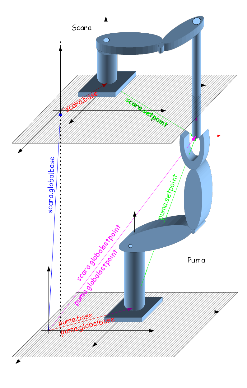
| | + | 给定SCARA和PUMA机器人在同一个生产单元中,SCARA机器人在PUMA机器人的上方: |
| | | | |
| − | ====一些最常用的点类型的类型分配表 ====
| |
| | | | |
| − | {| border = "1" valign = "top"
| + | [[File:Global Frames.png]] |
| − | |- valign="top" align = "center"
| |
| − | | || colspan="8" |'''master-robot'''
| |
| − | |-
| |
| − | |rowspan="8"|'''MF''' || || '''X''' || '''XY''' || '''XYZ''' || '''XYZR''' || '''XYZYPR''' || '''YPR''' || '''YP'''
| |
| − | |-
| |
| − | | '''X''' || p || p || p || p || p || p || p
| |
| − | |-
| |
| − | | '''XY''' || p || p || p || p || p || p || p
| |
| − | |-
| |
| − | | '''XYZ''' || p || p || p || p || p || p || p
| |
| − | |-
| |
| − | | '''XYZR''' || p || p || p || p/o/po || p || p || p
| |
| − | |-
| |
| − | | '''XYZYPR''' || p || p || p || p || p/o/po || o || p<br>(inactive)
| |
| − | |-
| |
| − | | '''YPR''' || p<br>(inactive) || p<br>(inactive) || p<br>(inactive) || p<br>(inactive) || o || o || p<br>(inactive)
| |
| − | |-
| |
| − | | '''YP''' || p<br>(inactive) || p<br>(inactive) || p<br>(inactive) || p<br>(inactive) || p<br>(inactive) || p<br>(inactive) || o
| |
| − | |-
| |
| − | |}
| |
| | | | |
| − | * p(3) 仅位置
| |
| − | * o(4) 仅姿态
| |
| − | * po(5) 位置和姿态
| |
| | | | |
| | + | === 使用全局坐标系 === |
| | | | |
| − | {{Note| 在由主机器人点类型不足以驱动的纯方向运动参考系的情况下,类型将被设置为位置(3),但是运动参考系将无效(不能运动}}
| + | 执行以下运动命令: |
| | | | |
| | + | '''Move scara target<br> |
| | + | '''Move puma target<br> |
| | + | 其中目标是点类型XYZYPR的位置<br> |
| | + | 将其转移到每个机器人的基本坐标系中: |
| | | | |
| − | [[File:AXY;MovingFrameType.png]]
| + | <u>对Scara:</u> |
| | | | |
| − | ====例子 1 ====
| + | target<sup>scara</sup><sub>B</sub> ← scara.gbase<sup>-1</sup>:target |
| − | <pre> | |
| − | common shared MF as moving frame of XYZR
| |
| − | MF.mastersource = SCARA.setpoint
| |
| − | </pre> | |
| − | 将MF.type自动设置为 '''5'''(位置和姿态 - 默认值)!
| |
| | | | |
| − | 尝试将其更改为主机不支持的值(例如MF.type = 0)源将返回错误:
| + | 其中 "←" 表示仅复制X,Y,Z和旋转坐标 |
| | | | |
| − | ====例子 2 ====
| |
| − | <pre>
| |
| − | common shared MF as moving frame of XYZR
| |
| − | common shared gXYZ as group axnm = a1 axnm = a2 axnm = a3 model=1 of XYZ
| |
| − | MF.mastersource = gXYZ.setpoint
| |
| − | </pre>
| |
| − | 在这种情况下,我们具有相同位置类型的情况,但是具有不同(或不存在)姿态类型的情况。 MF.type自动为'''3'''(仅位置)!
| |
| | | | |
| | + | <u>对Puma:</u> |
| | | | |
| − | ====例子 3 ==== | + | target<sup>puma</sup><sub>B</sub> = puma.gbase<sup>-1</sup>:target |
| − | <pre> | |
| − | common shared MF as moving frame of XYZYPR
| |
| − | common shared TILT as group axnm = a1 axnm = a2 axnm = a3 model=1 of YPR
| |
| − | MF.mastersource = TILT.setpoint
| |
| − | </pre> | |
| − | 在这种情况下,我们具有相同姿态类型但具有不同(或不存在)位置类型的情况。 MF.type自动为'''4'''(仅限姿态)!!
| |
| | | | |
| | + | 这里我们有"=" 符号,因为puma和全局坐标系具有相同的点类型 |
| | | | |
| | + | ==== 数字示例 ==== |
| | | | |
| − | ====例子 4 ====
| |
| | <pre> | | <pre> |
| − | common shared MF as moving frame of XYZ
| + | Move scara #{100,100,700,0,0,50} |
| − | common shared TILT as group axnm = a1 axnm = a2 axnm = a3 model=1 of YPR
| + | Move puma #{100,100,700,0,0,50} |
| − | MF.mastersource = TILT.setpoint
| |
| | </pre> | | </pre> |
| − | 在这种情况下,我们有两种点类型没有任何共同之处的情况 因此,类型将自动设置为3(仅位置)。
| |
| − |
| |
| − | = 新属性 =
| |
| − |
| |
| − | == 运动参考系基坐标偏移 ==
| |
| − | 主机和从机器人之间的相互空间关系(位置和姿态)由MF的BASE属性描述。<br>
| |
| | | | |
| − | * [[ MC-Basic:movingFrame.BASE| <moving-frame>.BASE]]是一个主机器人到从属的偏移量。 这是一个运动参考系的属性。
| + | 有: |
| | | | |
| − | == 对象位置 == | + | <pre>scara.gbase = #{0,100,700,0,0,0} |
| | + | scara.base = #{100,100,0,0} |
| | | | |
| − | 由两个机器人运动的对象或两个机器人的端点的相对位置彼此描述由'''[[ MC-Basic:movingFrame.OBJECTLOC| <moving-frame>.OBJECTLOC]]''' Moving-Frame属性。它描述从实际主站的源坐标(SetPoint或Here)中从站设定点的相对位置和姿态。它与父MF(或从机器人)保持相同的点类型。
| + | puma.gbase = #{0,0,0,0,0,0} |
| − | | + | puma.base = #{200,100,0,0,0,0} |
| − | 参考:[[ MC-Basic:movingFrame.OBJECTLOC| Object Location Property]]
| |
| − | | |
| − | {{Note| [[ MC-Basic:movingFrame.OBJECTLOC| OBJECTLOC]]可用于在连续的拾取和应用中更新新的接触点位置,类似于基于轴的MF的TRIGGER命令。}}
| |
| − | | |
| − | = 主从关系 =
| |
| − | | |
| − | 一旦设置了MF参数,则主站和从站位置之间的连接由以下公式定义。
| |
| − | <center>
| |
| − | '''slave.robot = MS2MF( MF.base<sup>-1</sup> : MF.MSource:MF.ObjectLoc )'''
| |
| − | </center>
| |
| − | | |
| − | 其中MF.MSource是<master> .setpoint或<master> .feedback
| |
| − | | |
| − | === MS2MF函数定义为 ===
| |
| − | | |
| − | '''M'''aster '''S'''ource to '''M'''aster '''F'''rame 函数: A = MS2MF(B) 定义为:
| |
| − | | |
| − | A->position = '''p-projection''' (B->position)<br>
| |
| − | A->orientation = B->orientation (''for MF.types: 4 and 5 only!'') <br>
| |
| − | | |
| − | * '''p-projection'''是简单的矩阵乘法,形式如下: '''A->position = TranslationTransformation * B->position'''
| |
| − | | |
| − | | |
| − | <!-- this was original idea:
| |
| − | | |
| − | A->position = '''p-projection''' * B->position<br>
| |
| − | A->orientation= '''q-projection''' * [[AXY:MC-Basic:movingFrame.SLAVEORIENTATION|MF.SLAVEORINETATION]] * B->orientation
| |
| − | | |
| − | | |
| − | * The <nowiki>* MF.SLAVEORINETATION</nowiki> represents multiplication by rotation matrix (quaternion, orientation-vector) for additional orientation vector manipulation.
| |
| − | | |
| − | * '''p-projection''' is a simple projection mapping that copies (X,Y,Z) into/from (X,Y) coordinatewise (X to X, Y to Y, Z to Z).
| |
| − | * '''q-projection''' is orientation vector projection, using quaternions it is easily represented by:
| |
| − | <br>
| |
| − | | |
| − | if:
| |
| − | <math> Q_{XYZ} = \begin{bmatrix}
| |
| − | \varphi & , & \vec n_{xyz} \\
| |
| − | \end{bmatrix}
| |
| − | </math>
| |
| − | and:
| |
| − | <math> \vec n_{xyz} = \begin{bmatrix}
| |
| − | nx & ny & nz \\
| |
| − | \end{bmatrix}
| |
| − | </math>
| |
| − | | |
| − | <br>
| |
| − | Then:
| |
| − | <math> Q_{XYZ} := {qprojection} (Q_{XY} ) = \begin{bmatrix}
| |
| − | \varphi & , & \vec n_{xy} \\
| |
| − | \end{bmatrix}
| |
| − | </math>
| |
| − | where <math> \vec n_{xy} </math> by projecting the unit vector <math> \vec n_{xyz} </math> tot he XY plane and normalizing it again.
| |
| − | | |
| − | In other words the unit vector of orientation will be immersed into other's robot work-space (keeping it normalized, i.e. ||n|| = 1) while keeping the same rotation angle <math> \varphi </math>.
| |
| − | | |
| − | Due to the fact that projected unit orientation vector is in the same half-space the actual rotation angel sign will be updated.
| |
| − | | |
| − | For example:
| |
| − | | |
| − | Having Yaw-Pitch-Roll space with angles: #{0, 180,90} (vector turned down with roll of 90 degrees) will be projected into Roll space as:
| |
| − | | |
| − | <nowiki>#{-90}</nowiki> = '''q-projection''' (#{0, 180,90}) , this due to the fact that n<sub>xyz</sub> is projected into [0,0,-1]
| |
| − | | |
| − | -->
| |
| − | | |
| − | == 点类型转换 ==
| |
| − | | |
| − | <u>Translation Transformation</u>
| |
| − | | |
| − | 与普通轴相反 - MF机器人—MF可以具有与从动机器人不同的点类型。为了将位置从MF点类型转换为从机器人点类型[[MC-Basic:movingFrame.TranslationTransformation|'''<moving-frame>.TranslationTransformation''']]定义3x3双矩阵属性。
| |
| − | | |
| − | * 定义了MF.MasterSource的点类型到MF的机器人类型的平移(位置)部分的变换矩阵。
| |
| − | * 矩阵阶数通过MF和主机器人的位置维度自动调整。
| |
| − | <br>
| |
| − | | |
| − | {| border = "1"
| |
| − | |-
| |
| − | | || Master-Source: XY ||Master-Source: XYZ
| |
| − | |-
| |
| − | |MF-type: XY || TranslationTransformation[1-2][1-2] || TranslationTransformation[1-2][1-3]
| |
| − | |-
| |
| − | |MF-type: XYZ || TranslationTransformation[1-2][1-3] || TranslationTransformation[1-3][1-3]
| |
| − | |}
| |
| − | | |
| − | | |
| − | 例如, 定义:<br>
| |
| − | <pre>
| |
| − | common shared MF as moving frame of XYZYPR
| |
| − | MF.MasterSource = GXY
| |
| − | </pre>
| |
| − | 自动定义:
| |
| − | | |
| − | [[MC-Basic:movingFrame.TranslationTransformation|TranslationTransformation]][*][*] = <math>
| |
| − | \begin{bmatrix}
| |
| − | 1 & 0 \\
| |
| − | 0 & 1 \\
| |
| − | 0 & 0 \\
| |
| − | \end{bmatrix}
| |
| − | </math>
| |
| − | | |
| − | or: '''TranslationTransformation is 2x3 matrix!'''
| |
| − | | |
| − | {{Note| 在MF的位置坐标数少于MasterSource的情况下,剩余的坐标将由 '''MF.BASE''' 相应的坐标值分配。}}
| |
| − | | |
| − | | |
| − | | |
| − | <!-- This was just an idea but I want to keep it here as a reminder:
| |
| − | | |
| − | === Orientation Transformation ===
| |
| − | | |
| − | * defines a matrix for the transformation of the orientation part '''from''' MF.MasterSource's point-type '''to the''' MF's robot-type.
| |
| − | * the matrix dimension is automatically adjusted by position dimension of MF and the master-source robot.
| |
| − | * automatic matrix-dimension adjustment:
| |
| − | | |
| − | {| border = "1"
| |
| − | |-
| |
| − | | || Master-Source: Roll ||Master-Source: Pitch Roll || Master-Source: Yaw Pitch Roll
| |
| − | |-
| |
| − | |MF-type: Roll || TranslationTransformation[1][1] || TranslationTransformation[1-2][1] || TranslationTransformation[1-3][1]
| |
| − | |-
| |
| − | |MF-type: Pitch Roll || TranslationTransformation[1][1-2] || TranslationTransformation[1-2][1-2] || TranslationTransformation[1-3][1-2]
| |
| − | |-
| |
| − | |MF-type: Yaw Pitch Roll || TranslationTransformation[1][1-3] || TranslationTransformation[1-2][1-3] || TranslationTransformation[1-3][1-3]
| |
| − | |}
| |
| − | | |
| − | | |
| − | for example:<br>
| |
| − | defining:
| |
| − | <pre>
| |
| − | common shared MF as moving frame of XYZR
| |
| − | MF.MasterSource = PUMA.Setpoint
| |
| | </pre> | | </pre> |
| − | automatically defines:
| |
| − |
| |
| − | [[AXY:MC-Basic:movingFrame.OrientationTransformation|OrientationTransformation]][*][*] = <math>
| |
| − | \begin{bmatrix}
| |
| − | 0 & 0 & 1 \\
| |
| − | \end{bmatrix}
| |
| − | </math>
| |
| − |
| |
| − | or: '''OrientationTransformationis 3x1 matrix!'''
| |
| − |
| |
| − | == Point Type transformations ==
| |
| − |
| |
| − | Contrary to the ordinary axes-MF robot-MF can have different point type from the slaved robot. In order to transform from MF point type into slave-robot point type new property has been defined. The transformation is looking for the closest location inside slave-robot working space.
| |
| − |
| |
| − |
| |
| − | === Slave Orientation ===
| |
| − |
| |
| − | '''[[AXY:MC-Basic:movingFrame.SLAVEORIENTATION|MF.SLAVEORIENTATION]]''' is a fixed type YPR (Yaw-Pitch-Roll, See: [[AXY:Kinematics_Package#XYZ_Yaw_Pitch_Roll|Yaw Pitch Roll]]) orientation vector used to rotate moving frame orientation vector into slave-robot orientation coordinates.
| |
| − |
| |
| − | Let's define the product of moving frame master source as intermediate SR variable:
| |
| − |
| |
| − | SR := ( MF.base<sup>-1</sup> : MF.MSource:MF.ObjectLoc )
| |
| − |
| |
| − | then the SR variable will be of the same point-type as the moving frame source MF.
| |
| − | in order to translate it into slave's robot command we do:
| |
| − |
| |
| − | slaverobot.position = '''p-projection'''(SR.position)<br>
| |
| − | slaverobot.oreintation = '''q-projection'''(MF.SLAVEORINTATION*SR.orientation)
| |
| − |
| |
| − | {{Note| In case when number of position coordinates of MF is less then of MasterSource the remaining coordinate will be assigned by the '''MF.BASE''' corresponding coordinate value.}}
| |
| − |
| |
| − | {{Note| In case when number of position coordinates of MF is less then of MasterSource the remaining coordinate will be assigned by the MF.base corresponding coordinate value.}}
| |
| − | -->
| |
| | | | |
| − | = 受影响(已更改)命令 =
| + | 我们获得'''SCARA'''的本地目标位置(在SCARA的基坐标系中): |
| | | | |
| − | == 激活(同步) ==
| |
| | | | |
| − | 设置'''[[MC-Basic:robot.SLAVE|<robot>.slave]] = 5'''将立即进入同步跟踪模式,不需要触发命令。由于基于机器人MF的工作窗口不存在,'''[[MC-Basic:movingFrame.ZERO|MF.ZERO]]''' 将在进入'''"slave=5"'''时返回当前的MF位置! 在此之后,从机器人将尝试与运动帧位置同步: '''MovingFrame(t) = MF(t) - MF(t0)'''<br>
| + | <nowiki>#</nowiki>{0,100,700,0,0,0}<sup>-1</sup> : #{100,100,700,0,0,50}为 #{'''100''' , '''0''' , '''0''' , 0 , 0 ,''' 50'''},可以写为:<br> |
| − | 其中t0是发出"slave=5" ''的时刻。
| + | <nowiki>#</nowiki>{100,0,0,50}← #{0,100,700,0,0,0}<sup>-1</sup> : #{100,100,700,0,0,50} |
| − | ''(参考:[[Element Coordination/Absolute Movements During Conveyor Tracking|Absolute_Movements_During_Conveyor_Tracking]])'' | + | 表示目标点在SCARA的基坐标系是: '''<u>#{100,0,0,50}</u>''' |
| | | | |
| − |
| + | '''PUMA'''机器人本地目标点以类似的方法计算: |
| | | | |
| − | 其中MF(.)是:
| + | <nowiki>#</nowiki>{200,100,0,0,0,0}<sup>-1</sup> : #{100,100,700,0,0,50}为 #{'''-100''' , '''0''' , '''700''' , 0 , 0 ,''' 50'''}, which we can write as:<br> |
| | + | <nowiki>#</nowiki>{-100,0,700,0,0,50}← #{200,100,0,0,0,0}<sup>-1</sup> : #{100,100,700,0,0,50} |
| | + | 表示目标点在PUMA机器人基坐标系上为: '''<u>#{-100,0,700,0,0,50}</u>''' |
| | | | |
| − | '''MF(t) = MS2MF( MF.base<sup>-1</sup> : Master(t):MF.ObjectLoc ) '''
| |
| | | | |
| − | Master(t) - 机器人主轴在时刻t的位置。<br>
| |
| − | '''MS2MF''' 在[[Element Coordination#MS2MF:|Master Source to Moving Frame function]]定义<br>
| |
| | | | |
| − | 与MC-Basic语言变量的关系是显而易见的:
| + | {{Note| PUMA运动学中的GBASE和BASE表示相同的事情,尽管可以给出不同的值(然后使用组合gbase:base),但强烈建议仅使用一个,另一个保留为零,即:#{0,0,0,0,0,0} }} |
| | | | |
| − | <nowiki><mf>.</nowiki>'''here''' = MF(t)
| + | === 使用基于机器人的运动参考系 === |
| | | | |
| − | <nowiki><mf>.</nowiki>'''zero''' = MF(0) ''(参考[[MC-Basic:movingFrame.ZERO|MovingFrame.ZERO]])''
| + | 可以使用基于机器人的运动参考系实现相同的功能示例。 |
| | | | |
| | + | 我们假设PUMA机器人是主机器人: |
| | | | |
| − | This means that the total slave robot motion of the slave robot that began to track (slave=5, synced or not) is the SAME as position of free slave robot (slave=0) '''IF''' the master robot did not move. In other words, if you want to teach some points on a moving object connected to the master robot just stop the master robot and move the slave to its desired destination on the object.
| + | common shared MF as Moving Frame of XYZR |
| | | | |
| − |
| |
| − | {{Note|Movement to MF.ZERO after initialization of tracking causes the slave robot to synchronize exactly to the master robot's location.}}
| |
| − |
| |
| − | == Deactivation(DeSyncing) ==
| |
| − |
| |
| − | Setting '''[[MC-Basic:robot.SLAVE|<robot>.slave]] = 0''' immediately enters into de-synchronization mode, which smoothly reduces tracking velocity to zero. (The part of the velocity induced by tracking not the velocity of added movements).
| |
| − |
| |
| − | {{Note| In robot-based MF's de-syncing is done using initial values of the movement in cartesain space (position, velocity, acceleration) using the parameters below:<br>
| |
| − |
| |
| − | * [[MC-Basic:robot.VELOCITYDESYNCTRAN|VELOCITYDESYNCTRAN]] , [[MC-Basic:robot.VELOCITYDESYNCROT|VELOCITYDESYNCROT]]<br>
| |
| − | * [[MC-Basic:robot.ACCELERATIONDESYNCTRAN|ACCELERATIONDESYNCTRAN]] , [[MC-Basic:robot.ACCELERATIONDESYNCROT|ACCELERATIONDESYNCROT]]<br>
| |
| − | * [[MC-Basic:robot.JERKDESYNCTRAN|JERKDESYNCTRAN]] , [[MC-Basic:robot.JERKDESYNCROT|JERKDESYNCROT]]<br>
| |
| − |
| |
| − | It is possible to activated syncing to another robot or just a plane movement during de-syncing. (Same as axes-based MF's)
| |
| − |
| |
| − | }}
| |
| − |
| |
| − | == Is Moving Frame Synchronized ==
| |
| − | The ''[[MC-Basic:robot.ISMOVINGFRAMESYNCHRONIZED| Is-Moving-Frame-Synchronized]]'' flag will have the same function as in axis-based MF's.
| |
| − |
| |
| − |
| |
| − | == Tracking Parameters ==
| |
| − |
| |
| − | The parameters:
| |
| − |
| |
| − | * '''VelocityMaxTrans, VelocityMaxRot, AccelerationMaxTrans, AccelerationMaxRot, JerkMaxTrans, JerkMaxRot''' <br>
| |
| − | * '''Dampingfactor, FilterFactor, MaxFlops'''<br>
| |
| − |
| |
| − | will be used in the same way as in axis-based MF's. Instead of acting on a scalar distance(<math>dp</math>) between master axis and tracking variable, <u>cartesian distance</u> (<math>\vec dp = \vec p_{master} - \vec p_{track}</math>) and Euler's angle distance (<math>\vec de = \vec e_{master} - \vec e_{track}</math>) between master robot position and slave-robot master tracking variable will be used for building criteria of stressful synchronization.
| |
| − |
| |
| − | == Trigger ==
| |
| − | As in robot-based MF's the concept of working-window and entering an object into it '''does not exist''', the
| |
| − | [[MC-Basic:TRIGGER| Trigger]] command '''will have no effect''' on robot-based moving frames. The actual moment of tracking will start always with setting of '''slave=5''' independently of previously used trigger command.
| |
| − |
| |
| − | == NOI ==
| |
| − | In case of MF-robot '''[[MC-Basic:movingFrame.NUMBEROFITEMS|NOI]]''' will return always '''-1'''.
| |
| − |
| |
| − | == Is In Window ==
| |
| − | [[MC-Basic:movingFrame.ISINWINDOW| Is In Window]] flag will return always 1 (true), actually there is no concept of working windows in this type of MF.
| |
| − |
| |
| − | == Unused Moving-Frame properties ==
| |
| − |
| |
| − | * '''Upstream, Downstream, Upmaster, Downmaster''' <br>
| |
| − | As the working-window concept does not exist in robot-based MF's these properties will have absolutely no influence on MF-robot operation.
| |
| − |
| |
| − | ==Next Item command ==
| |
| − |
| |
| − | * [[MC-Basic:NEXTITEM|'''NEXTITEM''']] command will have no effects on MF-robot operation.
| |
| − |
| |
| − | = Moving Frame Coordinate Transformations =
| |
| − |
| |
| − | Slave robot is connected to a master through Moving-Frame assigned to the slave's master frame property:
| |
| − | <pre>
| |
| − | <slaverobot>.MasterFrame = <master frame>
| |
| − | </pre>
| |
| − |
| |
| − | Master frame is a link between slave and master robot. It Includes definition of the master-source which can be either robot Cartesian command point ('''SETPOINT''') or robot's Cartesian feedback ('''HERE'''):
| |
| − |
| |
| − | <pre>
| |
| − | <master frame>.MasterSource = <masterrobot>.SETPOINT
| |
| − | </pre>
| |
| − |
| |
| − | == BASE transformation ==
| |
| − |
| |
| − | Master frame defines spacial relationship (distance and rotation) of the slave's robot frame to the master: '''<Master Frame>.Base'''
| |
| − |
| |
| − | [[File:COOP 2 ROB BASE.png|700px|border| Two robots with a defined distance between them using MF.BASE]]<br>
| |
| − |
| |
| − | == Defining an Object ==
| |
| − |
| |
| − | In total the object is held by two robots from two sides. Looking from the master's coordinate frame we have two points (in master-robot's '''world(robot)''' frame):
| |
| − |
| |
| − | <pre>
| |
| − | <masterrobot>.setpoint
| |
| − | <masterrobot>.setpoint:<movingframe>.objectloc
| |
| − | </pre>
| |
| − |
| |
| − | The second point of the object can be also reached through salve robot by (viewed by master-robot's '''world(robot)''' frame):
| |
| − | <pre>
| |
| − | <movingframe>.base:<slaverobot>.setpoint
| |
| − | </pre>
| |
| − |
| |
| − | [[File:COOP 2 ROB OBJ.png|700px|border|Usage of OBJECTLOC]]
| |
| − |
| |
| − | <Moving Frame>.ObjectLoc is location property of the Moving Frame data-object of the same point-type as the moving frame.
| |
| − | For example, it means if the moving frame was declared as '''XYZR''' (''common shared MF as moving frame of XYZR''), the OBJECTLOC will be also location of '''XYZR''' type.
| |
| − |
| |
| − | The OBJECTLOC specifies position and orientation of the slave's end-effector relative to the master's end point (Master Frame actually).
| |
| − |
| |
| − | == Example of complete slave command calculation ==
| |
| − |
| |
| − | [[File:COOP 2 ROB FRM.png|700px|border|Frame calculations in two-robot case.]]
| |
| − |
| |
| − |
| |
| − | mf.base = '''#{100,100,0,45}''' <br>
| |
| − | mf.base<sup>-1</sup> = '''#{-141,100,0,-45}'''<br>
| |
| − | mf.objectloc = '''#{80,0,0,180}'''<br>
| |
| − | master.setpoint = '''#{130,-72,0,0}'''<br>
| |
| − |
| |
| − | slave.setpoint = '''mf.base<sup>-1</sup>:master.setpoint:mf.objectloc'''<br>
| |
| − | slave.setpoint = '''#{-43 , -200 , 0 ,135 }'''<br>
| |
| − |
| |
| − |
| |
| − | * The above calculations are true in case both robots are of same (XYZR) point-type and the default MF.type value (''5- both position and orientation'') is used.
| |
| − |
| |
| − | == Example of three robots working on a same object ==
| |
| − |
| |
| − | Here is an example of three-robot cooperation. One robot is defined as a master and the other two are slaves. Each of the slave robots is connected through it's master frame to the master robot on different distances from it and on different gripper-points on the object.
| |
| − |
| |
| − | [[File:COOP 3 ROB.png|700px|border|Frame Calculation in three-robot case]]
| |
| − |
| |
| − | In this example we will define two Moving frame with each of them having a different OBJECTLOC.
| |
| − |
| |
| − | The first Moving Frame:
| |
| − | <pre>
| |
| − | Common Shared MF1 As Moving Frame Of XYZR
| |
| − | MF1.MasterSource = <masterrobot>.SETPOINT
| |
| − | MF1.BASE = #{..., ..., ..., 0}
| |
| − | MF1.OBJECTLOC = #{L,..., ..., 180}
| |
| − | </pre>
| |
| − |
| |
| − | The second Moving Frame:
| |
| | <pre> | | <pre> |
| − | Common Shared MF2 As Moving Frame Of XYZR
| + | MF.MSource = puma.setppoint |
| − | MF2.MasterSource = <masterrobot>.SETPOINT
| + | MF.OBJECTLOC = #{0,0,0,0} |
| − | MF2.BASE = #{..., ..., ..., 0}
| + | MF.BASE = Inverse(#{0,100,700,0,0,0}) |
| − | MF2.OBJECTLOC = #{SQRT(3)*L,L/2, ..., -150}
| + | scara.MasterFrame = MF |
| | + | scara.slave = 5 |
| | </pre> | | </pre> |
| | | | |
| − | * '''Assuming the object is even-sided (Equilateral) triangle of the side length L.'''
| + | 现在发行:<br> |
| − | | |
| − | {{Note| The orientational part of the second object-location MF's it is -150 degrees. The first slave's robot Xtool axis is in exactly opposite direction to the master's Xtool axis. And the second slave robot's Ytool axis is in exactly opposite direction to the master's Ytool axis.}}
| |
| − | | |
| − | = Algorithms and Software design =
| |
| − | | |
| − | * The master slave relationship is based on the same principleas in robot-based MF's as in axis-based MF's. The underling idea is to have same sort of movement if the MF is standing or moving.The principals are described here: [[Element Coordination/Absolute Movements During Conveyor Tracking|Absolute_Movements_During_Conveyor_Tracking]]<br>
| |
| − | | |
| − | * Axis-based moving frame tracking algorithm based on predicting the rendezvous point and limiting the motion by velocity, acceleration and jerk constant is described here: [[AXY:Element Coordination/One Dimensional Tracking Algorithm|One_Dimensional_Tracking_Algorithm]]<br>
| |
| − | | |
| − | * Same algorithm (tracking) applied on 3-dimensional position vector (Euler angles) is explained here: [[AXY:Element Coordination/Multi Dimensional Tracking Algorithm (Position)|Position_Tracking_Algorithm]]<br>
| |
| − | | |
| − | * Same algorithm (tracking) applied on 3-dimensional orientation vector is explained here: [[AXY:Element Coordination/Multi Dimensional Tracking Algorithm (Orientation)|Orientation_Tracking_Algorithm]]<br>
| |
| − | | |
| − | * Concept of '''global frame''' coordinate system as addition to '''base''' and '''world(robot)''' frames for multiple robot usage is described here:[[Element Coordination/Global Coordinates|Global Coordinates]]
| |
| | | | |
| − | * Enlargement of axis-based MF data structures is shown here: [[AXY:Element Coordination/Software Design| Software_Design]]<br>
| + | Move puma target<br> |
| | + | ''和''<br> |
| | + | Moves MF.zero<br> |
| | | | |
| − | <!-- == Issues List: ==
| + | 将puma和scara移动到同样的位置(目标)。<br> |
| − | {{Bugzilla|5954}}<br>
| |
| − | {{Bugzilla|5955}}<br>
| |
| − | {{Bugzilla|5957}}<br>
| |
| − | {{Bugzilla|5960}}<br>
| |
| − | {{Bugzilla|5963}}<br>
| |
| − | {{Bugzilla|6058}}<br>
| |
| − | {{Bugzilla|6075}}<br>
| |
| − | -->
| |
| − | | |
| − | = Examples =
| |
| − | | |
| − | == Example 1. two different robot kinematics ==
| |
| − | | |
| − | Cooperation between two unequal robot kinematics.
| |
| − | | |
| − | [[File:AXY;SCARAPUMA_COO.png|700px|border|Cooperation between SCARA and PUMA robot kinematics, PUMA robot is the master frame here]]
| |
| − | | |
| − | | |
| − | Moving Frame definition:
| |
| − | <pre>
| |
| − | Common Shared MF as Moving Frame of XYZR
| |
| − | </pre>
| |
| − | | |
| − | Linking it to the source (master):
| |
| − | <pre>
| |
| − | MF.MasterSource = Puma.Setpoint
| |
| − | </pre>
| |
| − | | |
| − | The master-source is a robot(PUMA) of point-type XYZYPR and the linked robot(SCARA) or the MF is of XYZR point type. In this case the MF.type will be automatically set to 3 (position only). <u> Orientation angle changes of the master robot will have no effects on the slave.</u> So we need to define transformation matrix:
| |
| − | | |
| − | | |
| − | <center>
| |
| − | | |
| − | <math>
| |
| − | | |
| − | \begin{bmatrix}
| |
| − | X \\
| |
| − | Y \\
| |
| − | Z \\
| |
| − | \end{bmatrix}
| |
| − | = \begin{bmatrix}
| |
| − | 1 & 0 & 0 \\
| |
| − | 0 & 1 & 0 \\
| |
| − | 0 & 0 & 1 \\
| |
| − | \end{bmatrix}
| |
| − | \cdot
| |
| − | \begin{bmatrix}
| |
| − | X \\
| |
| − | Y \\
| |
| − | Z \\
| |
| − | \end{bmatrix}
| |
| − | </math>
| |
| − | | |
| − | </center>
| |
| − | | |
| − | | |
| − | Or in the code:
| |
| − | | |
| − | <pre>
| |
| − | ' First column:
| |
| − | MF.TranslationTransformation[1][1]=1
| |
| − | MF.TranslationTransformation[2][1]=0
| |
| − | MF.TranslationTransformation[3][1]=0
| |
| − | ' Second column:
| |
| − | MF.TranslationTransformation[1][2]=0
| |
| − | MF.TranslationTransformation[2][2]=1
| |
| − | MF.TranslationTransformation[3][2]=0
| |
| − | ' Third column:
| |
| − | MF.TranslationTransformation[1][3]=0
| |
| − | MF.TranslationTransformation[2][3]=0
| |
| − | MF.TranslationTransformation[3][3]=1
| |
| − | </pre>
| |
| − | | |
| − | | |
| − | And then the offsets definitions:
| |
| − | | |
| − | The XY coordinates will be offseted for (10,10) mm:
| |
| − | <pre>
| |
| − | MF.base = #{10,10,0,0}
| |
| − | </pre>
| |
| − | | |
| − | A distance of 100mm between the two robots tool-tips is defined as:
| |
| − | <pre>
| |
| − | MF.ObjectLoc = #{0,0,100,0}
| |
| − | </pre>
| |
| − | | |
| − | | |
| − | and the tracking (master-slave) is defined by:
| |
| − | <pre>
| |
| − | Scara.Masterframe = MF
| |
| − | </pre>
| |
| − | and started:
| |
| − | <pre>
| |
| − | Scara.slave = 5
| |
| − | </pre>
| |
| − | | |
| − | == Example 2. SCARA and a tilting table==
| |
| − | | |
| − | | |
| − | [[File:AXY;SCARA_TILT.png]]
| |
| − | | |
| − | Moving Frame definition :
| |
| − | <pre>
| |
| − | Common Shared MF as Moving Frame of XYZR
| |
| − | </pre>
| |
| − | | |
| − | | |
| − | Having a tilt table robot (Object Having only Yaw and Pitch angle):
| |
| − | <pre>
| |
| − | Common Shared TiltTable As Group Axnm = Ax5 Axnm = Ax6 Model = 1 of YP
| |
| − | </pre>
| |
| − | | |
| − | Linking it to the source (master):
| |
| − | <pre>
| |
| − | MF.MasterSource = TilTable.Setpoint
| |
| − | </pre>
| |
| − | | |
| − | The master-source is a tilt-table of point-type YP and the linked robot or the MF is of XYZR point type. The MF.type will be automatically set to 3 (position only).
| |
| − | | |
| − | Transformation matrix for position actually does not exist as the TiltTable have no position component! So there is nothing to be set here.
| |
| − | | |
| − | | |
| − | And then the offsets definitions:
| |
| − | | |
| − | The XY coordinates will be offseted for 200 mm:
| |
| − | <pre>
| |
| − | MF.base = #{-200,0,0,0}
| |
| − | </pre>
| |
| − | | |
| − | | |
| − | | |
| − | Defining the object-location of 100mm makes the '''trick!'''
| |
| − | | |
| − | mf.base = '''#{Xb,Yb,Zb,Rb}''' <br>
| |
| − | mf.objectloc = '''#{Xo,Yo,Zo,0}'''<br>
| |
| − | master.setpoint = '''#{yaw,pitch}'''<br>
| |
| − | | |
| − | slave.setpoint = '''mf.base<sup>-1</sup>:master.setpoint:mf.objectloc'''<br>
| |
| − | | |
| − | '''i.e. the vector [Xo,Yo,Zo] will be rotated by the tilt-table angles [yaw,pitch]!!!'''
| |
| − | | |
| − | and the tracking (master-slave) is defined by:
| |
| − | <pre>
| |
| − | Scara.Masterframe = MF
| |
| − | </pre>
| |
| − | and started:
| |
| − | <pre>
| |
| − | Scara.slave = 5
| |
| − | </pre>
| |
| − | | |
| − | == Example 3. Two SCARA's working on a same piece ==
| |
| − | | |
| − | A robot to robot tracking example:<br>
| |
| − | Two SCARA robots, one master the other is slave.<br>
| |
| − | [[File:COOP 2 ROB SYNC.png|700px|border|Case of tracking with two SCARA robots.]]<br><br>
| |
| − | <u>Setup:</u><br>
| |
| − | set the slave robot to track the master on a distance of 100mm pointing in face-to face direction (180º)
| |
| − | <pre>
| |
| − | Common Shared MF as Moving Frame Of XYZR
| |
| − | MF.MasterSource = ScaraMaster
| |
| − | MF.ObjectLoc = #{100,0,0,180}
| |
| − | ScaraSlave.MovingFrame = MF
| |
| − | ScaraSlave.Slave=5
| |
| − | </pre>
| |
| − | At the moment of engagement (i.e. '''Slave=5''') Zero point is recorded!<br>
| |
| − | <br><br><br>
| |
| − | <u>Wait to be Synchronized and arriving to master-position together:</u> <br>
| |
| − | ''System waits until MF is synchronized ([[MC-Basic:robot.ISMOVINGFRAMESYNCHRONIZED|Is-Moving-Frame-Synchronized]] equals 1)'' '''and''' ''motion towards Zero point is completed ([[MC-Basic:group.ISMOVING|isMoving]] flag is not positive)''
| |
| − | <pre>
| |
| − | Moves MF.Zero
| |
| − | While ScaraSlave.IMFS <> 1 and ScaraSlave.Ismoving > 0
| |
| − | Sleep 1
| |
| − | End While
| |
| − | </pre><br>
| |
| − | <u>Do something, or just stay in tracking mode.</u><br><br><br>
| |
| − | <u>Stopping.</u>De-Synchronize: <br>
| |
| − | <pre>
| |
| − | slave = 0
| |
| − | while ScaraSlave.IMFS <> 0
| |
| − | Sleep 1
| |
| − | End While
| |
| − | </pre>
| |
| − | After this ScaraSlave will be stopped not exactly on the ScaraMaster's path ''(deviation is more or less random and depends on the master's robot path and joints' deceleration parameters)''.<br>
| |
| − | <br>
| |
| − | | |
| − | == Example 4. Coordination ==
| |
| − | Relative position between the robots during tracking, the slave robot to track the master on a distance of 100mm pointing in face-to face direction (180º)
| |
| − | | |
| − | [[File:COOP 2 ROB SYNC TOOL.png|700px|border|Coordination.]]
| |
| − | zoomed detail:
| |
| − | [[File:COOP 2 ROB SYNC BIG.png|400px|border|Coordination detail]]
| |
| − | | |
| − | [[Category:Motion:MovingFrame]]
| |
| − | | |
| − | | |
| − | == Example 5. PUMA and SCARA on a patch placement job ==
| |
| − | | |
| − | | |
| − | [[File:Coordination.png|700px|border|Setup.]]
| |
| − | | |
| − | For setting up global; coordinates see: [[Element Coordination/Global Coordinates#Example|Global_Coordinates]]
| |
| − | | |
| − | [[File:Coordination detail.png|700px|border|Detail view of work-space locations]]
| |
| − | | |
| − | | |
| − | === Geometry ===
| |
| − | | |
| − | [[File:Coordination Geometry.png|700px|border| Geometric Setup.]]
| |
| − | | |
| − | Also see: [[Element Coordination/Global Coordinates#numeric_example|Global_Coordinates]]
| |
| − | | |
| − | the given setup can be accomplished in four different ways:
| |
| − | {| border = "1" valign = "top"
| |
| − | |- valign="top" align = "center"
| |
| − | | World(Robot) Frame || Base Frame || Global Base || Moving Frame
| |
| − | |- valign="top"
| |
| − | |
| |
| − | puma.base = #{0,0,0,0,0,0} <br>
| |
| − | scara.base = #{0,0,0,0} <br>
| |
| − | Moves puma #{50,0,600,90,90,0}<br>
| |
| − | Moves scara #{-100,-100,0,0}
| |
| − | ||
| |
| − | puma.base = #{200,100,0,0,0,0} <br>
| |
| − | scara.base = #{100,100,0,0} <br>
| |
| − | Moves puma #{250,100,600,90,90,0}<br>
| |
| − | Moves scara #{200,0,-100,0}
| |
| − | ||
| |
| − | puma.base = #{200,100,0,0,0,0} <br>
| |
| − | puma.gbase = #{0,0,0,0,0,0} <br>
| |
| − | scara.base = #{100,100,0,0} <br>
| |
| − | scara.gbase = #{0,100,700,0} <br>
| |
| − | Moves puma #{250,100,600,90,90,0}<br>
| |
| − | Moves scara #{250,100,600,90,90,0}<br>
| |
| − | ||
| |
| − | puma.base = #{200,100,0,0,0,0} <br>
| |
| − | scara.base = #{100,100,0,0} <br>
| |
| − | puma.globalbase = #{0,0,0,0,0,0}<br>
| |
| − | scara.globalbase = #{0,0,0,0,0,0}<br>
| |
| − | Moves puma #{250,100,600,90,90,0}<br>
| |
| − | MF.MasterSource = puma.setpoint<br>
| |
| − | MF.Base = #{200,0,-600,0}<br>
| |
| − | MF.ObjectLoc = #{0,0,50,0}<br>
| |
| − | scara.MasterFrame = MF<br>
| |
| − | scara.slave = 5<br>
| |
| − | Moves scara MF.zero<br>
| |
| − | |-
| |
| − | |}
| |
| − | | |
| − | {{Note|'''''All four given code examples will bring the two robots to same positions!'''''}}
| |
| − | | |
| − | {{Note/Important| The "Moving Frame" example takes into account SCARA base coordinates and not the global ones as the MF is declared of XYZR point type.}}
| |
| − | | |
| − | === System setup ===
| |
| − | | |
| − | definitions:
| |
| − | | |
| − | <pre>
| |
| − | Common Shared MF As Moving Frame Of XYZR
| |
| − | Common Shared hold As Location Of XYZR
| |
| − | Common Shared patch_feeder As Location Of XYZR
| |
| − | </pre>
| |
| − | | |
| − | initialization :
| |
| − | | |
| − | <pre>
| |
| − | SCARA.Base = #{100,100,0,0}
| |
| − | SCARA.GBASE = #{0,100,700,0,0,0}
| |
| − | PUMA.Base = #{200,100,0,0}
| |
| − | | |
| − | | |
| − | MF.MasterSource = PUMA.SETPOINT
| |
| − | MF.ObjectLoc = #{0,0,50,0}
| |
| − | MF.Base = #{200,0,-700,0}
| |
| − | | |
| − | SCARA.BlendingMethod = 2
| |
| − | SCARA.BlendingFactor = 80
| |
| − | SCARA.MasterFrame = MF
| |
| − | </pre>
| |
| − | | |
| − | === Execution Code ===
| |
| − | | |
| − | <pre>
| |
| − | while patches()
| |
| − | MoveS PUMA MoldPose((PatchNumber()))
| |
| − | MoveS SCARA patch_feeder
| |
| − | MoveS SCARA down
| |
| − | Call TakePatch(SCARA)
| |
| − | Moves SCARA up
| |
| − | Moves SCARA hold
| |
| − | MF.ObjectLoc = MoldProfile(PatchNumber())
| |
| − | SCARA.slave = 5
| |
| − | Moves SCARA MF.Zero
| |
| − | Call GluePatch(SCARA)
| |
| − | Moves SCARA up
| |
| − | SCARA.Slave = 0
| |
| − | Moves SCARA hold
| |
| − | end while
| |
| − | </pre>
| |
| − | | |
| − | === Functions and variables used in the program above:===
| |
| − | | |
| − | <pre>
| |
| − | Function MoldPose( n as long) as location of XYZYPR
| |
| − | </pre>
| |
| − | Function returning pathc position on the mold in PUMA's coordinate system (e.g. XYZYPR)
| |
| − | | |
| − | <pre>
| |
| − | Function MoldProfile( n as long) as location of XYZR
| |
| − | </pre>
| |
| − | Function returning the shape profile of the mold in XYZ coordinates , setting it into OBJECTLOC will effectively set a right position of the SCARA robot on the mold.
| |
| − | Returns SCARA locations (XYZR).
| |
| − | | |
| − | <pre>
| |
| − | Sub TakePatch(robot as generic group)
| |
| − | </pre>
| |
| − | Subroutine for taking (gripper manipulation, vacuum, waiting, etc) a patch from the feeder.
| |
| − | | |
| − | <pre>
| |
| − | Sub GluePatch(robot as generic group)
| |
| − | </pre>
| |
| − | Subroutine for placing the patch on the mold. Here included are all synchronizations needed (wait, gripper open, ...)
| |
| − | | |
| − | <pre>
| |
| − | MF.Base
| |
| − | </pre>
| |
| − | Moving Frame Base offset,
| |
| − | | |
| − | <pre>
| |
| − | hold
| |
| − | </pre>
| |
| − | Waiting position
| |
| − | | |
| − | <pre>
| |
| − | Patch_feeder
| |
| − | | |
| − | </pre>
| |
| − | Position from where the patches are taken.
| |
全局坐标概念
对于使用不同点类型的全局坐标概念的机器人已经被定义。 这允许以一种常见的独特格式给予机器人位置,以独立地观察机器人具有多少轴。 这里使用的关键属性是机器人的base变换,如Robot_Working_Frames所述
基坐标系属性
机器人有两个笛卡尔坐标系:世界(机器人)坐标系和基坐标系。
世界(机器人)坐标系
在由q = (q1,q2,q3, .... , qn)定义的机器人姿势中,n是机器人的NDOF。 世界(机器人)参考坐标由下式定义:
pworld = DirectKinematics (q)
其中p可以是:p =(x,y,z,偏航,俯仰,滚动)取决于机器人运动学。
 | NOTE |
| 为了简化讨论,我们假定该工具包含在正运动学计算中。这里省略了工件和工作台的坐标系。 |
基坐标系
基坐标系是由robot.base属性移动的世界(机器人)坐标系:
pbase = base:pworld
其中:是复合运算符。
全局基坐标属性(全局坐标)
所有用户输入(目标运动指令点,运动参考坐标等)都在基座坐标系中给出。 然而,这些系统可以与机器人不同(例如,R1具有XYZR和R2具有XYZYPR)。 因此,我们假设一个共同的(全局)基坐标系,将所有机器人转换到一个系统:
p1global = R1.glbalbase:R1.base:R1.DirectKinemaitcs(R1.pcmd)
p2global = R2.glbalbase:R2.base:R2.DirectKinemaitcs(R2.pcmd)
p3global = R3.glbalbase:R3.base:R3.DirectKinemaitcs(R3.pcmd)
...
pmglobal = Rm.glbalbase:Rm.base:Rm.DirectKinemaitcs(Rm.pcmd)
假设系统有m个机器人
这是通过添加始终与实际机器人点类型无关的<robot>.globalbase位置来实现的,在XYZYPR系统中给出
为了使全局坐标系尽可能的使用,运动命令(MOVE,MOVES,MOVESKD,CIRCLE ...)的扩展方式除了目前仅允许的机器人点类型的位置之外,还可以接受XYZYPR点类型的位置。
| NOTE |
| 给定的扩展适用于最多6个NDOF(不超过6个)的机器人。 |
| NOTE |
| 如果机器人点类型已经是XYZYPR,则全局和基本属性具有绝对相同的功能,可以相互添加。 他们都可以使用,但我们强烈建议只使用一个(而另一个保留为零),以减少混乱。 |
与此同时,还有两个新的属性:
例子
给定SCARA和PUMA机器人在同一个生产单元中,SCARA机器人在PUMA机器人的上方:
使用全局坐标系
执行以下运动命令:
Move scara target
Move puma target
其中目标是点类型XYZYPR的位置
将其转移到每个机器人的基本坐标系中:
对Scara:
targetscaraB ← scara.gbase-1:target
其中 "←" 表示仅复制X,Y,Z和旋转坐标
对Puma:
targetpumaB = puma.gbase-1:target
这里我们有"=" 符号,因为puma和全局坐标系具有相同的点类型
数字示例
Move scara #{100,100,700,0,0,50}
Move puma  #{100,100,700,0,0,50}
有:
scara.gbase = #{0,100,700,0,0,0}
scara.base  = #{100,100,0,0}

puma.gbase  = #{0,0,0,0,0,0}
puma.base   = #{200,100,0,0,0,0}
我们获得SCARA的本地目标位置(在SCARA的基坐标系中):
#{0,100,700,0,0,0}-1 : #{100,100,700,0,0,50}为 #{100 , 0 , 0 , 0 , 0 , 50},可以写为:
#{100,0,0,50}← #{0,100,700,0,0,0}-1 : #{100,100,700,0,0,50}
表示目标点在SCARA的基坐标系是: #{100,0,0,50}
PUMA机器人本地目标点以类似的方法计算:
#{200,100,0,0,0,0}-1 : #{100,100,700,0,0,50}为 #{-100 , 0 , 700 , 0 , 0 , 50}, which we can write as:
#{-100,0,700,0,0,50}← #{200,100,0,0,0,0}-1 : #{100,100,700,0,0,50}
表示目标点在PUMA机器人基坐标系上为: #{-100,0,700,0,0,50}
| NOTE |
| PUMA运动学中的GBASE和BASE表示相同的事情,尽管可以给出不同的值(然后使用组合gbase:base),但强烈建议仅使用一个,另一个保留为零,即:#{0,0,0,0,0,0} |
使用基于机器人的运动参考系
可以使用基于机器人的运动参考系实现相同的功能示例。
我们假设PUMA机器人是主机器人:
common shared MF as Moving Frame of XYZR
MF.MSource   = puma.setppoint
MF.OBJECTLOC = #{0,0,0,0}
MF.BASE      = Inverse(#{0,100,700,0,0,0})
scara.MasterFrame = MF
scara.slave  = 5
现在发行:
Move puma target
和
Moves MF.zero
将puma和scara移动到同样的位置(目标)。
