Difference between revisions of "PLS Timing Issues"
(→.HWassistance) |
|||
| (59 intermediate revisions by 4 users not shown) | |||
| Line 1: | Line 1: | ||
| − | = | + | <big><span style="color: red">'''Replaced by NEW PLS article - [[Programmable Limit Switch|Programmable Limit Switch]]'''</span></big> |
| − | |||
| − | + | <strike> | |
| − | |||
| − | == | + | ==Introduction == |
| − | + | This article describes timing issues of PLS triggering. | |
| − | + | The following variables affect PLS timing: | |
| − | * | + | *[[MC-Basic:element.POSITIONERRORDELAY| Axis.PositionErrorDelay]] |
| + | *[[MC-Basic:pls.HWASSISTANCE| PLS.HWAssistance ]] | ||
| + | *[[MC-Basic:pls.PLSPropagationDelay| PLS.PLSPropagationDelay ]] | ||
| − | + | Samples in motion profiles, in which the acceleration profile changes its basic formula (jerk discontinuity), will have an increased error in computing the inter-sample delay (Δt). This is due to the unavailability of an exact profile change parameter within one sample. In addition, higher-order (e.g., quadratic, cube, sine) acceleration profiles are not modeled in the inter-sample delay (Δt) calculations, and thus an error of JT3/6 is to be expected. | |
| − | + | '''An increased error in computing''' the inter-sample delay (Δt) will occur in all cases of non-linear acceleration change: | |
| − | |||
| − | |||
| − | |||
| − | |||
* sine acceleration | * sine acceleration | ||
* one-sample duration movements | * one-sample duration movements | ||
| − | * velocity | + | * trapezoidal velocity corners |
| − | * acceleration | + | * trapezoidal acceleration corners |
* extreme acceleration (so acc phase duration is 1 sample) or very short movement | * extreme acceleration (so acc phase duration is 1 sample) or very short movement | ||
| − | <center><gallery> | + | It is difficult to estimate the position error introduced, but it is typically around JT<sup>3</sup>/6. |
| + | |||
| + | <center><gallery widths=300px heights=200px perrow=12> | ||
Image:Axystems;Plstiming-acc.png|''Illustration 1: Error introduced due to the jerk value in s'''ine-acceleration''' profile at the transition sample between acceleration saturation and acceleration decrease'' | Image:Axystems;Plstiming-acc.png|''Illustration 1: Error introduced due to the jerk value in s'''ine-acceleration''' profile at the transition sample between acceleration saturation and acceleration decrease'' | ||
| − | Image:Axystems;Plstiming-tracc.png|''Illustration 2: Error introduced due to the acceleration change in ''' | + | Image:Axystems;Plstiming-tracc.png|''Illustration 2: Error introduced due to the acceleration change in '''trapezoidal acceleration''' profile at the transition sample between acceleration saturation and acceleration decrease'' |
| − | Image:Axystems;Plstiming-trvel.png|''Illustration 3: Error introduced due to the transition point between cruise velocity and deceleration in ''' | + | Image:Axystems;Plstiming-trvel.png|''Illustration 3: Error introduced due to the transition point between cruise velocity and deceleration in '''trapezoidal velocity''' profile'' |
</gallery></center> | </gallery></center> | ||
| − | + | <br/>{{Note | In cases of extremely short motions (velocity or acceleration too high or path length too short) even if user commanded sine-acceleration profile the system will automatically change it to trapezoidal velocity. }}<br/> | |
| − | + | {{Note | PLS will always be triggered too late if it is triggered by a feedback source such as PFB or PEXT. But in this case no additional delay should be added! }}<br/> | |
| − | {{Note | | ||
| − | |||
| − | |||
== Buffering == | == Buffering == | ||
| − | + | The delay of the motion bus forces the system to postpone the switching of the PLS output. Therefore, the detected PLS output switch events are stored in the buffer and executed after the estimated delay. | |
| − | |||
| − | |||
| − | |||
| − | |||
| − | |||
| − | |||
| − | |||
| − | |||
| − | |||
| − | |||
| − | |||
| − | |||
| − | |||
| − | |||
| − | |||
| − | |||
| − | |||
| − | |||
| − | Two | + | Two different buffers ('''per each PLS''') are dedicated to the PLS delayed outputs: |
| − | + | * Motion Bus PLS Delay buffer. Used for storing PLS-delays through multiple sampling periods. The size of this buffer is: 4*10. | |
| + | * Digital Output Microsecond Delay buffer. Used for storing microsecond delays of only one motion bus sample. The size of this buffer is '''4 ''' and it is hardware defined.<br/> | ||
| − | + | <br/>{{Note|In systems with a relatively large motion bus delay <nowiki>(PositionErrorDelay >> 3)</nowiki> number of the stored PLS switches can be greater than the Motion Bus Delay Buffer size. In this case error 3298 will be returned: '''"The PLS positions are too close to each other and/or the velocity is too high for output to toggle"'''. If one sampl has more than 4 PLS, IO error 21011 will be returned: '''"Too many PLS toggling requested "'''.}}<br/> | |
| + | == Debug Variables == | ||
| − | + | Two read-only properties returning in microseconds the time of the IO toggle. | |
| + | [[MC-Basic:pls.HWIOtime|PLS.HWIOtime ]] | ||
| − | + | [[MC-Basic:pls.PLSdelaytime| PLS.PLSdelaytime]] | |
| − | == | + | == PLS-Timing Diagram == |
<center> | <center> | ||
| Line 83: | Line 63: | ||
| − | [[Category | + | [[Category:Motion Control]] |
| − | [[Category | + | <!-- [[Category:Motion:PLS]] --> |
| − | [[Category | + | <!-- [[Category:Motion:HW-PLS]] --> |
| − | + | </strike> | |
Latest revision as of 11:17, 16 October 2018
Replaced by NEW PLS article - Programmable Limit Switch
Introduction
This article describes timing issues of PLS triggering.
The following variables affect PLS timing:
Samples in motion profiles, in which the acceleration profile changes its basic formula (jerk discontinuity), will have an increased error in computing the inter-sample delay (Δt). This is due to the unavailability of an exact profile change parameter within one sample. In addition, higher-order (e.g., quadratic, cube, sine) acceleration profiles are not modeled in the inter-sample delay (Δt) calculations, and thus an error of JT3/6 is to be expected.
An increased error in computing the inter-sample delay (Δt) will occur in all cases of non-linear acceleration change:
- sine acceleration
- one-sample duration movements
- trapezoidal velocity corners
- trapezoidal acceleration corners
- extreme acceleration (so acc phase duration is 1 sample) or very short movement
It is difficult to estimate the position error introduced, but it is typically around JT3/6.
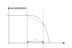
Illustration 1: Error introduced due to the jerk value in sine-acceleration profile at the transition sample between acceleration saturation and acceleration decrease
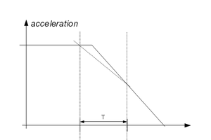
Illustration 2: Error introduced due to the acceleration change in trapezoidal acceleration profile at the transition sample between acceleration saturation and acceleration decrease
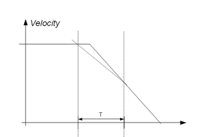
Illustration 3: Error introduced due to the transition point between cruise velocity and deceleration in trapezoidal velocity profile


| NOTE | |
| In cases of extremely short motions (velocity or acceleration too high or path length too short) even if user commanded sine-acceleration profile the system will automatically change it to trapezoidal velocity. |
| NOTE | |
| PLS will always be triggered too late if it is triggered by a feedback source such as PFB or PEXT. But in this case no additional delay should be added! |
Buffering
The delay of the motion bus forces the system to postpone the switching of the PLS output. Therefore, the detected PLS output switch events are stored in the buffer and executed after the estimated delay.
Two different buffers (per each PLS) are dedicated to the PLS delayed outputs:
- Motion Bus PLS Delay buffer. Used for storing PLS-delays through multiple sampling periods. The size of this buffer is: 4*10.
- Digital Output Microsecond Delay buffer. Used for storing microsecond delays of only one motion bus sample. The size of this buffer is 4 and it is hardware defined.
| NOTE | |
| In systems with a relatively large motion bus delay (PositionErrorDelay >> 3) number of the stored PLS switches can be greater than the Motion Bus Delay Buffer size. In this case error 3298 will be returned: "The PLS positions are too close to each other and/or the velocity is too high for output to toggle". If one sampl has more than 4 PLS, IO error 21011 will be returned: "Too many PLS toggling requested ". |
Debug Variables
Two read-only properties returning in microseconds the time of the IO toggle.
PLS-Timing Diagram
