Project Example: Flip Flop (Ladder Diagram)
| Language: | English • 中文(简体) |
|---|
The task's purpose is to set and reset an output.
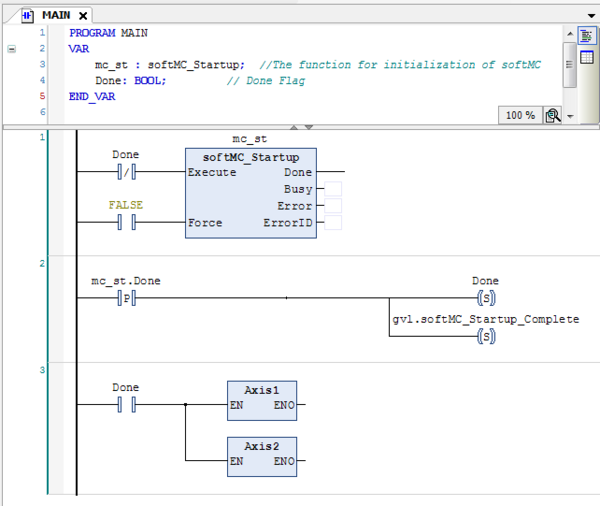
The main program initializes a startup process in the softMC.
After the startup process is done, the program sets 'Done' variable and a global variable.
After 'Done' variable is set, programs 'Axis1' and 'Axis2' are called.
The application uses two drives and their outputs.
After installation of device description file (created by the Configurator) to Device Repository, the drive's address will be declared in the Axis Pool:
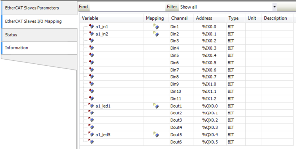
In the EtherCAT Slaves section, we can find the I/O mapping for each device.
In the picture below Input1, Input2, Output1, Output5 are declared as new variables (can also be mapped as existing variables):
The main program uses 'softMC_Startup' FB ('mc_st' Instance) to initialize a startup process in the softMC.
A rising edge detection will set the 'Done' variable (and also a global variable) and then call programs 'Axis1' and 'Axis2':
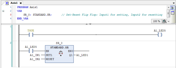
When programs 'Axis1' and 'Axis2' are called, output5 is turned on.
If output5 is turned on, the 'SR' FB is enabled with output1 as 'Q1' ('SR_0' Instance).
Input1 will trigger the 'set' function and input2 will trigger the 'reset' function.
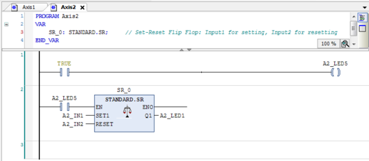
Programs 'Axis1' and 'Axis2' are similar:
Visualization
The program is controlled by a graphic interface:
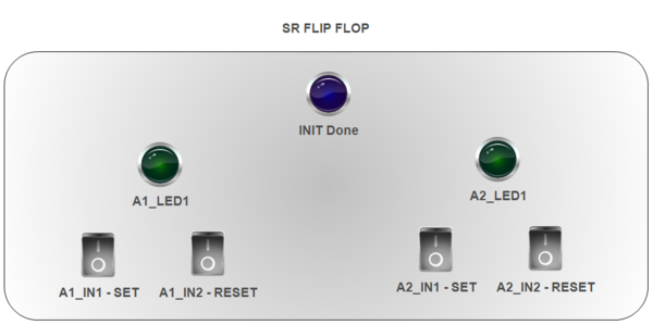
When the startup process of softMC is done, the blue lamp is turned on.
The user can set and reset the outputs of the two drives with special buttons for each function. In addition, the result of the 'SR' FB is shown by the green lamps.


