Difference between revisions of "PUMA robot"
(→Singular points) |
|||
| Line 1: | Line 1: | ||
| + | {{Languages|PUMA_robot}} | ||
= PUMA robot model = | = PUMA robot model = | ||
Revision as of 03:56, 29 May 2017
| Language: | English • 中文(简体) |
|---|
Contents
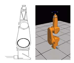
PUMA robot model
The PUMA robot is a six – degrees of freedom articulated robot of the following joints:

Coupling
In Staubli RX robot family there is a mechanical coupling between axes 5 and 6. The coupling matrix of the robot is defined by:

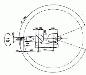
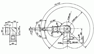
RX90 Work-Space
Puma work-space from above
Puma work-space from aside
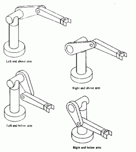
Puma Lefty-Righty configurations


The PUMA WORLD workspace is limited by joint limits and the following auxiliary cartesian boundaries, available for the user:
- RMAX – maximum radius of a cartesian point (), no points beyond this radius are allowed.
- RMIN - smallest radius of a cartesian point (). No points inside this radius are allowed.
- ZMIN – z coordinate of the robot base plane. No points below this plane are allowed.

Robot configurations
Every robot location can be achieved in at least 8 different joint positions (the number can be greater counting also different joint positions obtained by changing joint angles for full revolutions (360 degrees)). Different joint coordinates of one location are called robot configurations. The PUMA robot configurations are defined by three flags: arm, elbow and wrist. Each flag has its command and feedback value: acmd/afbk, ecmd/efbk, wcmd/wfbk. Command values (acmd, ecmd, efbk) describe the given target point configuration of a movement (can be both nodal and modal). The feedback values (afbk, efbk, wfbk) represent the current robot configuration (pfb – values), and these are read-only flags.
The arm flag defines LEFTY or RIGHTY configurations according:
RIGHTY – positive jont-2 moves the wrist in positive WORLD Z direction while joint-3 is not activated
LEFTY– positive jont-2 moves the wrist in negative WORLD Z direction while joint-3 is not activated
The elbow flag defines ABOVE or BELOW configurations according:
ABOVE - position of the wrist of the arm with respect to the shoulder coordinate system has coordinate value along the Y axis of the second segment


BELOW - position of the wrist of the arm with respect to the shoulder coordinate system has coordinate value along the Y axis of the second segment

The wrist flag defines FLIP or NOFLIP configuration according:
---
FLIP – value of joint 5 is negative
NOFLIP – value of joint 5 is positive
Command configuration flags of PUMA robot and their influence on motion are given by:
| Flag(shortname) | |
|
|
| ArmCmd (acmd) | |
|
|
| ElbowCmd (ecmd) | |
|
|
| WristCmd (wcmd) | |
|
|
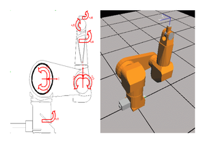
Singular points
Singular points are joint points where robot configurations can not be determined, these are robot positions where a small difference in one of the joint angles introduce change in robot configuration.
Looking from the other side, from the WORLD-space coordinates. In the vicinities of these points, small changes in location coordinates can introduce big changes in joint coordinates. Therefore moving in cartesian-interpolated mode (MOVES, PASS-THROUGH, CIRCLE) through these points can result in strong increase of joint velocities.
| WARNING | |
| Note that non-zero a3 parameter change position of singularity. See: Elbow_Singularity_of_PUMA_robots |
Typical RX90 poses
Configuration of the robot at the "ready position" Joint: {0, -90, 0, 0, 0, 0} Cartesian: #{0 , 0 , 985 , 0 , 0 , 0}
Configuration of the robot at the "zero position"Joint: {0,0,0,0,0,0}:Cartesian: #{450, 0 , 535, 0, 0, 0}
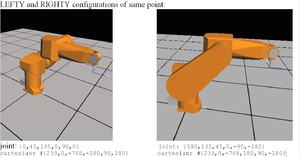
LEFTY and RIGHTY configurations of same point: joint: {0,45,135,0,90,0} joint: {180,135,45,0,-90,-180}cartesian: #{233,0,-768,-180,90,180} cartesian: #{233,0,-768,180,90,-180}
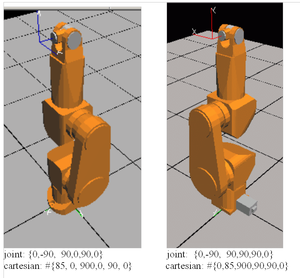
joint: {0,-90, 90,0,90,0} joint: {0,-90, 90,90,90,0} cartesian: #{85, 0, 900,0, 90, 0} cartesian: #{0,85,900,90,90,0}


Usually in robotics DH parameters are used to describe the robot geometry. We are using the following definition of DH parameters:
- θ i is the joint angel from the xi-1 axis to the xi axis about the z i-1 axis (using the right-hand rule).
- α i is the offset angle from z i-1 axis to the z i axis about xi axis (using the right hand rule).
- ai is the offset distance from the intersection of the z i-1 axis with the xi axis to the origin of the ith frame along xi axis (or the shortest distance between the z i-1 and z I axes).
- di is the distance from the origin of the (i-1)th coordinate frame to the intersection of the z i-1 axis with the xi axis along z i-1 axis.


For RX90 family of Staubli robots we have:
| |
|
|
| |
|
|
| |
|
|
| |
|
|
| |
|
|
| |
|
|
| |
|
|
The above parameters of link matrix property of the robot must be filled-in in the robot’s setup file. In order that the system accepts the above setup the “configgroup” command must be executed. Note that only the above set of parameters affects the robot geometry, the rest of the link[][] and axis[][] values do not influence the robot geometry in any way and are not affected (changed) by configgroup command or any other robot command.
The rest of the DH parameters are predefined as follow and are automatically internally set by choosing the right group model.
| |
|
|
| |
|
|
| |
|
|
| |
|
|
| |
|
|
| |
|
|
| |
|
|
Orientation Angles
